Do you have a question about the Sony CDX-L250 and is the answer not in the manual?
Details power output, harmonic distortion, CD player, tuner, and amplifier specs.
Covers FM/AM tuning ranges, sensitivity, CD player performance, and laser diode specs.
Lists outputs, tone controls, power requirements, dimensions, and mass.
Crucial notes on handling components, laser safety, and general warnings.
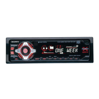
Identifies controls, covers unit reset, clock setting, and disc playback.
Guidelines for disc handling, CD-R compatibility, and general operational precautions.
Explains display items, repeat/shuffle play, and radio station storage.
Covers sound adjustments, bass enhancement, and quick attenuation features.
Illustrates the connection diagram and provides essential installation notes.
Covers installation precautions, frequency switch, mounting, and reset procedures.
Step-by-step guide for removing the front panel assembly.
Detailed steps for disassembling the CD mechanism and removing the main board.
Instructions for removing the heat sink and chassis sub-assembly.
Steps for disassembling the lever section and removing the servo board.
Guide for disassembling the shaft roller and floating block assemblies.
Steps for disassembling the optical pick-up block.
How to activate test mode and perform FM auto scan/stop level adjustments.
Procedures for adjusting FM stereo separation and AM auto scan/stop level.
Detailed pin assignments for the system controller IC.
Illustrates the signal flow and functional blocks of the CD playback system.
Shows the functional blocks and signal paths for the tuner system.
Covers the display block diagram and the physical placement of circuit boards.
Detailed circuit schematic for the CD mechanism.
Component layout diagram for the main section's printed wiring board.
Part one of the detailed circuit schematic for the main section.
Component layout diagram for the display section's printed wiring board.
Exploded view illustrating the chassis and its associated parts.
Exploded view detailing the components of the front panel assembly.
First part of the exploded view for the CD mechanism.
Second part of the exploded view for the CD mechanism.
Third part of the exploded view for the CD mechanism.
Lists components for the display section, including LEDs and diodes.
Enumerates various semiconductor parts like LEDs, diodes, and ICs used in the unit.
Lists capacitors and resistors used on the main board.
Lists transistors, switches, connectors, and other components for the main board.
Lists capacitors, connectors, and vibrators for the servo board.
Lists parts for SL SW board, miscellaneous items, and hardware.
Details various screws and hardware used in the unit's assembly.
Lists specific parts required for unit installation and external connections.
| Brand | Sony |
|---|---|
| Model | CDX-L250 |
| Category | Car Receiver |
| Language | English |