3
TABLE OF CONTENTS
1. GENERAL
Location of controls................................................................. 4
Getting Started......................................................................... 4
CD Player ................................................................................ 4
Radio ....................................................................................... 5
Other Functions ....................................................................... 5
Connections ............................................................................. 7
2. DISASSEMBLY
2-1. Front Panel Assy ................................................................. 9
2-2. CD Mechanism Block ....................................................... 10
2-3. Main Board ....................................................................... 10
2-4. Heat Sink ........................................................................... 11
2-5. Chassis (T) Sub Assy ........................................................ 11
2-6. Lever Section .................................................................... 12
2-7. Servo Board....................................................................... 12
2-8. Shaft Roller Assy .............................................................. 13
2-9. Floating Block Assy .......................................................... 13
2-10. Optical Pick-up Block ....................................................... 14
3. ELECTRICAL ADJUSTMENTS................................. 15
4. DIAGRAMS
4-1. IC Pin Description............................................................. 17
4-2. Block Diagram –CD Section–........................................... 19
4-3. Block Diagram –Tuner Section– ....................................... 20
4-4. Block Diagram –Display Section– .................................... 21
4-5. Circuit Boards Location .................................................... 21
4-6. Printed Wiring Boards –CD Mechanism Section–............ 22
4-7. Schematic Diagram –CD Mechanism Section– ................ 24
4-8. Printed Wiring Board –Main Section– .............................. 25
4-9. Schematic Diagram –Main Section (1/2)– ........................ 26
4-10. Schematic Diagram –Main Section (2/2)– ........................ 27
4-11. Printed Wiring Board –Display Section– .......................... 28
4-12. Schematic Diagram –Display Section–............................. 29
5. EXPLODED VIEWS
5-1. Chassis Section ................................................................. 32
5-2. Front Panel Section ........................................................... 33
5-3. CD Mechanism Section (1) ............................................... 34
5-4. CD Mechanism Section (2) ............................................... 35
5-5. CD Mechanism Section (3) ............................................... 36
6. ELECTRICAL PARTS LIST ........................................ 37
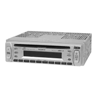
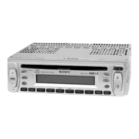
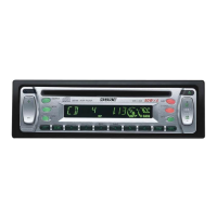
CDX-L250/L430X
w
w
w
.
x
i
a
o
y
u
1
6
3
.
c
o
m
Q
Q
3
7
6
3
1
5
1
5
0
9
9
2
8
9
4
2
9
8
T
E
L
1
3
9
4
2
2
9
6
5
1
3
9
9
2
8
9
4
2
9
8
0
5
1
5
1
3
6
7
3
Q
Q
TEL 13942296513 QQ 376315150 892498299
TEL 13942296513 QQ 376315150 892498299
http://www.xiaoyu163.com
http://www.xiaoyu163.com