EasyManua.ls Logo

Sony CDX-GT40U Service Manual

Sony CDX-GT40U
66 pages
To Next Page IconTo Next Page
Page #1 background imageLoading...
Page #1 background image
SERVICE MANUAL
Sony Corporation
Published by Sony Techno Create Corporation
SPECIFICATIONS
US, Canadian, E, Mexican, Argentina, Korean, Indian model
FM/AM COMPACT DISC PLAYER
AEP, Russian, UK model
FM/MW/LW COMPACT DISC PLAYER
Saudi Arabia model
FM/MW/SW COMPACT DISC PLAYER
9-893-214-05
2012G33-1
©
2012.07
US Model
CDX-GT40U/GT40UW
Canadian Model
CDX-GT40U
AEP Model
UK Model
CDX-GT40U/GT44U
E Model
CDX-GT45U
Russian Model
CDX-GT40U/GT42UE/GT47UE
Indian Model
CDX-GT44U
Ver. 1.4 2012.07
The tuner and CD sections have no adjustments.
AUDIO POWER SPECIFICATIONS
(US model)
CEA2006 Standard
Power Output: 17 Watts RMS 4 at
4 Ohms < 1 % THD + N
SN Ratio: 80 dBA
(reference: 1 Watt into 4 Ohms)
Model Name Using Similar Mechanism NEW
CD Drive Mechanism Type MG-101CA-188
Optical Pick-up Name DAX-25A
Tuner section
FM
Tuning range:
US, CND, AR model: 87.5 – 107.9 MHz
AEP, UK, EA model:
87.5 – 108.0 MHz
E, MX, KR, IND model:
87.5 – 108.0 MHz (at 50 kHz step)
87.5 – 108.0 MHz (at 100 kHz step)
87.5 – 107.9 MHz (at 200 kHz step)
RU model:
FM1/FM2: 87.5 – 108.0 MHz (at 50 kHz)
FM3: 65 – 74 MHz (at 30 kHz)
FM tuning step:
E, MX, KR, IND model:
50 kHz/100 kHz/200 kHz switchable
Antenna (aerial) terminal:
External antenna (aerial) connector
Intermediate frequency: 25 kHz
Usable sensitivity: 8 dBf
Selectivity: 75 dB at 400 kHz
Signal-to-noise ratio: 80 dB (stereo)
Separation: 50 dB at 1 kHz
Frequency response: 20 – 15,000 Hz
AM (US, CND, E, MX, AR, KR, IND model)
Tuning range:
US, CND, AR model: 530 – 1,710 kHz
E, MX, KR, IND model:
531 – 1,602 kHz (at 9 kHz step)
530 – 1,710 kHz (at 10 kHz step)
AM tuning step:
E, MX, KR, IND model:
9 kHz/10 kHz switchable
Antenna (aerial) terminal:
External antenna (aerial) connector
Intermediate frequency:
US, CND, AR model:
9,115 kHz or 9,125 kHz/5 kHz
E, MX, KR, IND model:
9,124.5 kHz or 9,115.5 kHz/4.5 kHz
(at 9 kHz step)
9,115 kHz or 9,125 kHz/5 kHz
(at 10 kHz step)
Sensitivity: 26 V
MW/LW (AEP, RU, UK model)
MW (EA model)
Tuning range:
MW: 531 – 1,602 kHz
LW: 153 – 279 kHz (AEP, RU, UK model)
Antenna (aerial) terminal:
External antenna (aerial) connector
Intermediate frequency:
9,124.5 kHz or 9,115.5 kHz/4.5 kHz
Sensitivity: MW: 26 V
LW: 45V (AEP, RU, UK model)
SW (EA model)
Tuning range:
SW1: 2,940 – 7,735 kHz
SW2: 9,500 – 18,135 kHz
(except for 10,140 – 11,575 kHz)
Antenna (aerial) terminal:
External antenna (aerial) connector
Intermediate frequency:
9,124.5 kHz or 9,115.5 kHz/4.5 kHz
Sensitivity: 26 μV
– Continued on next page –
CDX-GT40U/GT40UW/GT42UE/
GT44U/GT45U/GT47UE
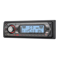
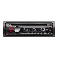
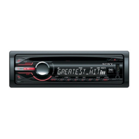
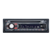
Photo: CDX-GT40U: AEP, UK model
CD player section
Signal-to-noise ratio: 120 dB
Frequency response: 10 – 20,000 Hz
Wow and utter: Below measurable limit
USB Player section
Interface: USB (Full-speed)
Maximum current: 1 A
Power ampli er section
Outputs: Speaker outputs
Speaker impedance: 4 – 8 ohms
Maximum power output:
US, CND, E, EA, MX, AR, KR, IND model:
52 W 4 (at 4 ohms)
AEP, RU, UK model: 45 W 4 (at 4 ohms)

Other manuals for Sony CDX-GT40U

Question and Answer IconNeed help?

Do you have a question about the Sony CDX-GT40U and is the answer not in the manual?

Sony CDX-GT40U Specifications

General IconGeneral
MP3 playbackYes
Tuner typeSSIR-EXA
FM band range87.5 - 107.9 MHz
Supported radio bandsAM, FM
Impedance220 Ω
Output power52 W
Product colorBlack
Ready for iPodNo
Disc types supportedCD, CD-R, CD-RW
Audio output channels4.0 channels
Signal-to-Noise Ratio (SNR)80 dB
Display typeLCD
USB version2.0
USB ports quantity1
File typeMP3/WMA/AAC
Number of optical discs1 discs
Weight and Dimensions IconWeight and Dimensions
Weight1200 g
Dimensions (WxDxH)178 x 180 x 50 mm

Summary

SERVICE MANUAL

AUDIO POWER SPECIFICATIONS

Details CEA2006 standard power output and SN ratio for US models.

SPECIFICATIONS

Lists technical specifications for FM/AM, MW/LW/SW tuners and CD player sections.

General

Abbreviation

Defines abbreviations used for model designations.

NOTES ON CHIP COMPONENT REPLACEMENT

Important notes regarding the replacement of chip components.

SAFETY-RELATED COMPONENT WARNING!

Warning about safety-critical components and replacement procedures.

SERVICE NOTE

UNLEADED SOLDER

Information and precautions regarding the use of unleaded solder.

NOTES ON HANDLING THE OPTICAL PICK-UP BLOCK OR BASE UNIT

Guidelines for safely handling the optical pick-up block.

NOTES ON LASER DIODE EMISSION CHECK

Instructions for safely checking the laser diode emission.

TEST DISCS

Lists required test discs for operation and checks.

EXTENSION CABLE AND SERVICE POSITION

NOTE FOR REPLACEMENT OF THE USB CONNECTOR (CN902) AND THE AUX JACK (J901)

Procedure for replacing USB connector and AUX jack.

CLEANING THE CONNECTORS

Method for cleaning connectors between the unit and front panel.

NOTE THE MAIN BOARD OR SYSTEM CONTROLLER (IC501) REPLACING

Destination Setting

Step-by-step guide for setting the destination code.

Confirmation After Destination Setting

Method to confirm the correct destination setting was applied.

ABOUT THE MG-101CA-188 OF FORMER AND NEW

New/Former Discrimination

Visual guide to differentiate between former and new servo boards.

New/Former Compatibility

Table showing compatibility between mechanical block and servo board types.

ABOUT CHANGE OF THE LCD DRIVER IC (IC901) ON THE KEY BOARD

New/former discrimination

Methods to distinguish between new and former types based on serial number, part number, or IC.

CONNECTIONS

Connection diagram 3

Detailed diagram showing how to connect the unit to the car's power, antenna, and speakers.

Notes on the control and power supply leads

Important notes regarding control and power supply leads.

Notes on speaker connection

Crucial notes for connecting speakers correctly.

CDX-GT40U: AEP, UK model/GT44U: AEP, UK model

Connection diagram 3

Wiring diagram and connection details for specific models.

Warning

Warning about potential damage to the antenna.

Notes on the control and power supply leads

Notes on power and control leads for these models.

CDX-GT40U: Russian model/GT42UE/GT47UE

Схема подсоединения 3

Wiring diagram and connection details for specific models.

Предостережение

Warning about potential damage to the antenna.

О проводах управления и питания

Notes on power and control leads for these models.

CDX-GT44U: Indian model/GT45U: E, Saudi Arabia, Mexican, Korean model

Connection diagram 3

Wiring diagram and connection details for specific models.

Warning

Warning about potential damage to the antenna.

Notes on the control and power supply leads

Notes on power and control leads for these models.

CDX-GT45U: Argentina model

Connection diagram 3

Wiring diagram and connection details for the Argentina model.

Warning

Warning about potential damage to the antenna.

Notes on the control and power supply leads

Notes on power and control leads for this model.

SECTION 3 DISASSEMBLY

3-1. SUB PANEL ASSY

Procedure for disassembling the sub panel assembly.

3-2. CD MECHANISM BLOCK

3-3. MAIN BOARD

3-4. SERVO BOARD

3-5. CHASSIS (T) SUB ASSY

3-6. ROLLER ARM ASSY

3-7. CHASSIS (OP) ASSY

3-8. CHUCKING ARM SUB ASSY

3-9. SLED MOTOR ASSY

3-10. OPTICAL PICK-UP SECTION

3-11. OPTICAL PICK-UP

SECTION 4 DIAGRAMS

4-1. BLOCK DIAGRAM - Main Section -

Block diagram illustrating the main section of the unit's circuitry.

4-2. BLOCK DIAGRAM - DISPLAY Section

THIS NOTE IS COMMON FOR PRINTED WIRING BOARDS AND SCHEMATIC DIAGRAMS.

For Printed Wiring Boards.

Notes and cautions specifically for printed wiring boards.

For Schematic Diagrams.

Notes and conventions used in schematic diagrams.

Waveforms

Displays waveforms for key ICs on the main board.

4-3. PRINTED WIRING BOARD - MAIN Section (1/2) (Except Saudi Arabia Model)

4-4. PRINTED WIRING BOARDS - MAIN Section (2/2) (Except Saudi Arabia Model)

4-5. SCHEMATIC DIAGRAM - MAIN Section (1/5) -

4-6. SCHEMATIC DIAGRAM - MAIN Section (2/5) -

4-7. SCHEMATIC DIAGRAM - MAIN Section (3/5)

4-8. SCHEMATIC DIAGRAM - MAIN Section (4/5) -

4-9. SCHEMATIC DIAGRAM - MAIN Section (5/5)

4-10. PRINTED WIRING BOARD - KEY Section -

4-11. SCHEMATIC DIAGRAM - KEY Section -

IC Block Diagrams

IC402 MM1836A333NRE (MAIN board (1/5))

IC1300 OZ539IGN-A1-0-TR (MAIN board (2/5))

IC681 NJM2878F3-15 (TE2) (MAIN board (5/5))

IC401 BD3467FV-E2 (MAIN board (3/5))

• IC Pin Function Description

MAIN BOARD (5/5) IC601 M321FEFG-7KN3 (SY (USB CONTROL)

MAIN BOARD (4/5) IC701 TC94A99FG-003 (SY) (DIGITAL SIGNAL PROCESSOR)

MAIN BOARD (5/5) IC601 M321FEFG-7KN3 (SY (USB CONTROL)

MAIN BOARD (5/5) IC601 M321FEFG-7KN3 (SY (USB CONTROL)

MAIN BOARD (5/5) IC601 M321FEFG-7KN3 (SY (USB CONTROL)

SECTION 5 EXPLODED VIEWS

5-1. MAIN SECTION

Exploded view of the main section of the unit.

5-2. FRONT PANEL SECTION

5-3. CD MECHANISM SECTION

SECTION 6 ELECTRICAL PARTS LIST

KEY

KEY MAIN

KEY

MAIN

MAIN

MAIN SENSOR SERVO

PARTS FOR INSTALLATION AND CONNECTIONS

SUPPLEMENT-1

Subject: PRINTED WIRING BOARD - MAIN board for Saudi Arabia model

Specifies the content of the supplement as the printed wiring board for Saudi Arabia model.

1. DIAGRAMS

For Printed Wiring Boards.

Notes and cautions specifically for printed wiring boards.

For Schematic Diagrams.

Notes and conventions used in schematic diagrams.

1-1. PRINTED WIRING BOARD - MAIN Section (1/2) -

1-2. PRINTED WIRING BOARD - MAIN Section (2/2) -

SUPPLEMENT-2

Subject: Change of KEY board (Suffix-21/-22)

Details changes related to the KEY board including part number changes.

1. NEW/FORMER DISCRIMINATION

Main unit (Bottom side) –

Method to distinguish by serial number on the main unit.

– KEY Board (Side A) –

Method to distinguish by part number on the key board (Side A).

– KEY Board (Side B) –

Method to distinguish by LCD driver IC on the key board (Side B).

2. DIAGRAMS

For Printed Wiring Boards.

Notes and cautions specifically for printed wiring boards.

For Schematic Diagrams.

Notes and conventions used in schematic diagrams.

2-1. PRINTED WIRING BOARD - KEY Board -

2-2. SCHEMATIC DIAGRAM - KEY Board -

3. ELECTRICAL PARTS LIST

KEY

KEY

REVISION HISTORY

Related product manuals