16
D-EJ250
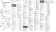
5-6. IC PIN FUNCTION DESCRINTION
Pin No. Pin Name I/O Description
• IC801 (SYSTEM CONTROL) T5AW5-04CD
1 GND – Ground terminal
2 XIN I System clock input
3 XOUT O Not used (OPEN)
4 TEST I Test mode terminal
5 VCPU_2.0V – Power supply
6 FOK_I I Focus OK signal input
7 XBUSY_I I Auto sequencer status signal input from BU9354CKV
8 RESET_I I Micon reset input
9 ACKCD_I I Not used (Fixed to L)
10 HP-L O Headphone/line switch signal output to AN17020B
11 SCOR_I I SCOR pulse input
12 HPSW_O O Headphone power switch signal output
13 DSP_SEL I DSP select signal input (Fixed to L)
14 XPOWLT_O O Data latch signal output to BH6580KV
15 SRW_O O Serial interface Read/Write signal output to BH9354CKV
16 SDTI_I I Serial data input from BU9354CKV
17 SDTO_O O Serial data output to BU9354CKV
18 SCK_O O Serial clock output to BU9354CKV
19 AVCPU – Power supply for CPU and I/O
20 ADVREF I Analog reference voltage for A/D converter
21 AD_SEL I Destination setting terminal
22 AD_CHGMNT I Charging monitor input
23 AD_KEY_2 I Set’s button detection input
24 AD_BATTMNT I Battery voltage monitor input
25 WP/AD_KEY1 I Set’s button detection input
26 WP/AD_RMKEY I Remocon’s button detection input
27 AD_DCINMNT I DC-IN voltage monitoring input
28 WP/XOPEN I OPEN switch status detection input
29 TUPWR_O O Not used (OPEN)
30 BEEP_O O BEEP sound output
31 NC O Not used (OPEN)
32 <VDD_EEPROM> – Power supply for EEPROM (Not used)
33 WP/K2_RM O Set’s button/remocon’s button select output
34 TU_ON_I I Not used (fixed at L)
35 VOL+ I “VOL+” button detection input
36 X4M/16M_I I DRAM size selection terminal (fixed at H)
37 TEST I Test terminal
38 VOL– I “VOL–” button detection input
39 LCD_REQ_O O Not used (OPEN)
40 HOLD_I I HOLD switch status detection input
41 to 56 SEG0 to 15 O LCD segment output
57 to 60 COM0 to 3 O LCD common output
61 to 63 V1 to 3 – Inner charge pump terminal
64 C1 – Inner charge pump terminal
65 C0 – Inner charge pump terminal
66 XWAKEUP_O O PGM wake-up signal output
 Loading...