DCR-PC109/PC109E
2-1 2-2
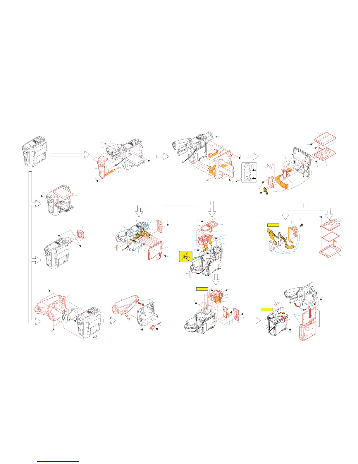
2-1. DISASSEMBLY
The following flow chart shows the disassembly procedure.
VC
-352
VC-352
1
2
1
2
3
4
5
6
8
7
1
2
1
Two screws (M1.7x3) black
2
P cabinet (C) (G) assembly
1
Two screws (M1.7x4) silver
2
Open the cassette lid.
3
Screw (M1.7x2.5) silver
4
Screw (M1.7x4) silver
1
Screw (M1.7x2.5) silver
2
Two screws (M1.7x4) silver
3
Two screws (M1.7x4) silver
4
Screw (M1.7x4) silver
5
FP-841 flexible board (26P)
1
Four screws (M1.7x2.5) silver
2
Eject knob
3
Two tapping screws (M1.7x3.5) black
4
Cabinet (G) section
1
Release the lock
2
Screw (M1.7x2.5) silver
3
Tapping screw (M1.7x3.5) black
3
1
1
4
5
3
6
2
2
4
1
1
Two screws (M1.4x2) black
2
Eye cup assembly
1
9
2
3
4
5
7
8
1
3
5
7
6
2
q;
2
3
8
6
7
9
q;
qa
1
1
5
6
8
qd
qg
qf
qh
9
q;
qa
qs
3
2
6
6
BT flexible adhesive sheet
7
FP-848 flexible board (22P)
8
FP-926 flexible board (6P)
9
FP-846 flexible board (51P)
q;
Cabinet (R) section
1
Tape (A)
2
Three tapping screws (M1.7x5) black
3
Hinge blind
4
Two screws (M1.7x3) black
5
Tapping screw (M1.7x3.5) blac
6
P cabinet (C) (G) assembly
7
Tape (A)
8
FP-848 flexible board (22P)
9
Screw (M1.7x2.5) black
q;
LCD panel section
qa
Hinge section
1
Microphone unit (MEGA) (6P)
2
Two screws (M1.7x2.5) silver
3
Cabinet (upper) (G) assembly
4
CR insulating sheet
5
Flexible board (from lens device) (29P)
6
FP-839 flexible board (33P)
7
Two screws (M1.7x2.5) silver
8
Lens block assembly
1
Screw (M1.7x4) silver
2
Rear panel assembly
3
Screw (M1.7x2.5) silver
4
Control switch block (SS6800) (18P)
5
Control switch block (SS6800)
6
FP-842 flexible board (20P)
7
FP-845 flexible board (10P)
8
FP-843 flexible board (39P)
9
Screw (M1.7x4) silver
q;
Tapping screw (M1.7x3.5) black
qa
Two screws (M1.7x4) silver
qs
EVF section
4
3
2
5
4
7
6
1
7
1
Screw (M1.7x4) silver
2
Rear panel assembly
3
CR shield sheet
4
Screw (M1.7x2.5) silver
5
to
qg
(CN9301 (20P), CN1201 (18P), CN1203 (10P), CN1208 (39P)
CN5001 (33P), CN9102 (27P), CN9103 (27P), CN5101 (29P),
CN1205 (20P), CN9101 (10P), CN6501 (10P)) of VC-352 board.
qh
VC-352 board
5
Claw
6
FP-840 board (16P)
7
Harness (RR-057) (2P)
8
Front panel assembly (G)
1
Tape (A)
2
FP-844 flexible board (20P)
3
Screw (M1.7x2.5) silver
4
Return the VC-352 board.
5
Four screws (M1.4x1.5) silver
6
Open the cassette lid.
7
VC-352 board, Mechanism deck.
7
4
q;
8
1
qa
3
5
9
6
2
7
8
qs
4
5
4
1
Screw (M1.7
×
2.5) silver
2
Four claws
3
Hinge cover (M), FP-926 flexible board
4
Hinge cover (C)
5
FP-848 flexible board,
Hinge (63) assembly
HELP 03
HELP 01
HELP 02
1
2
5
3
4
1
4
2
3
1
Control key block (SB6800) (6P)
2
Tapping screw (M1.7x5) black
3
Two claws
4
TP cushion
5
P cabinet (M) assembly
6
PD-213 board,
LCD unit (ACX528AKP-J),
Light guide plate block
5
6
4
Belt shaft
5
Belt bracket (front)
6
Grip belt assembly
SECTION 2
DISASSEMBLY


 To Next Page