EasyManua.ls Logo

Sony DCR-PC7 - Page 43

Sony DCR-PC7
107 pages
Print Icon
To Next Page IconTo Next Page
To Previous Page IconTo Previous Page
Loading...
6-4
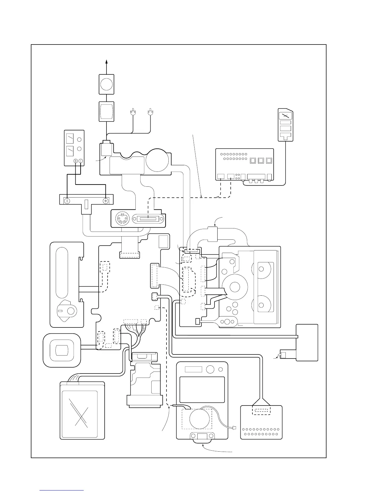
Fig. 6-1-3.
LCD block
Lens block
Must be connected
when changing the
mode settings in
the menu system.
ME4800
Cabinet (R)
CPC-6 terminal
board jig
(J-6082-371-A)
CPC-6 jig
(J-6082-370-A)
Zoom switch
Focus switch
FZ4800
switch block
View finder
VK4800 Operation switch block
CN1000
CN200
CN1002
CN1001
CN2301
CN6202
CN6201
VC-183 board
CN2300
CN3104
CN6103
MR-36
board
CN2703
CN3103
CN3102
CN3101
CN6102
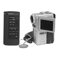
Adjusting remote
commander
Must be connected when
performing adjustments.
DD-91
board
Battery terminal
Regulated
power supply
(8.4
±
0.1Vdc)
VIDEO/AUDIO
HEADPHONE jack
Color
monitor
Vector
scope
AUDIO L
AUDIO R
Terminated
at 75
CN6200
CN3100
Extention
cable (18P)
(J-6082-374-A)
Microphone
26PIN
multi
connector
LANC
terminal
CN6101
I/O board-1 jig
(J-6082-372-A)
CC DOWN
switch
Speaker