6-11
20) Press the PAUSE button of the adjusting remote commander.
21) Set data: 03 to page: 6, address: 01, and press the PAUSE button
of the adjusting remote commander.
22) Read the DDS display data, and this data is named W
0. If W0
lies within the “85” to “89” range, perform “Processing after
completing adjustments”. If it lies outside the range, perform
the following adjustments.
23) Convert W
0 to decimal notation, and obtain W0´.
24) Calculate X
2´ using the following equations (decimal notation
calculation).
C´ = W
0´ – B´ – 21 ................................................ Equation 4
X
2´= ............ Equation 5
(X
1´ and B´ are values obtained from equations 2) and 3)
25) Convert X
2´ to hexadecimal notation and obtain X2.
(Round off to one decimal place)
26) Set data X
2 to page: F, address: 1E, and press the PAUSE button
of the adjusting remote commander.
27) Change the data of page: F, address: 1F, and adjust the DDS
display data to “87”.
28) Press the PAUSE button of the adjusting remote commander.
29) Set data: 01 to page: 6, address: 01, and press the PAUSE button
of the adjusting remote commander.
30) Check that the DDS display data lies within the “13” to “17”
range.
Processing after Completing Adjustments
1) Set data: 00 to page: D, address: 10, and press the PAUSE button
of the adjusting remote commander.
2) Set data: 00 to page: 1, address: 01.
3) Set data: 00 to page: 6, address: 01, and press the PAUSE button
of the adjusting remote commander.
4) Set data: 00 to page: 6, address: 04.
5) Set data: 00 to page: 6, address: 00.
6. Flange Back Adjustment
The inner focus lens flange back adjustment is carried out
automatically.
6-1. Flange Back Adjustment (1)
Adjusting method:
1) Check that at both the zoom lens TELE terminal and WIDE
terminal, the center of the chart for the flange back adjustment
and center of the exposure screen coincide.
2) Set data: 01 to page: 6, address: 00.
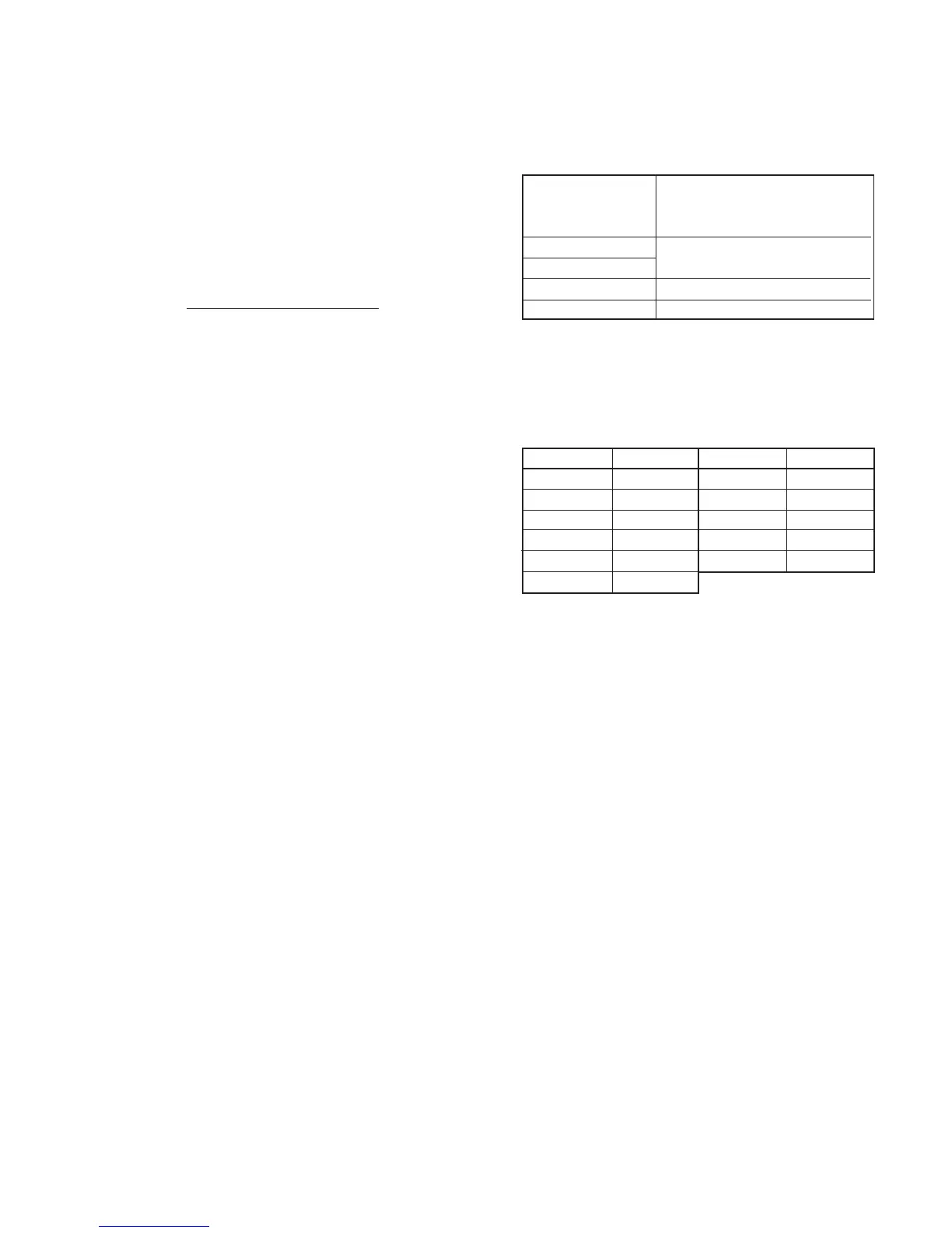
3) Check that the data of page: F, address: 24 to 29, 38 to 3B is the
initial value (see table below).
4) Check that the data of page: 6, address: 02 is 00.
5) Set data: 13 to page: 6, address: 01, and press the PAUSE button
of the adjusting remote commander.
6) Set data: 15 to page: 6, address: 01, and press the PAUSE button
of the adjusting remote commander.
(The adjustment data will be automatically input to page: F,
address: 24 to 29, 38 to 3C.)
7) Check that the data of page: 6, address: 02 is “01”.
Processing after Completing Adjustments
1) Turn OFF the main power supply (8.4V)
2) Perform “Flange Back Adjustment (2)”.
(114 – B´) x (X
1´ – 48) + 48 x C´
C´
Subject
Measurement Point
Measuring Instrument
Adjustment Page
Adjustment Address
Flange back adjustment chart
(2.0 m from the front of the lens)
(Luminance: 300 ± 50 lux)
Check operations on TV monitor
F
24 to 29, 38 to 3C
Address Data
20
00
19
00
1C
38
39
3A
3B
3C
Address Data
4A
15
90
19
82
13
24
25
26
27
28
29


 To Next Page
 Loading...