EasyManua.ls Logo

Sony DSC-F77 User Manual

Sony DSC-F77
61 pages
To Next Page IconTo Next Page
Page #1 background imageLoading...
Page #1 background image
SERVICE MANUAL
LEVEL 2
Link
SERVICE NOTE
DISASSEMBLY
BLOCK DIAGRAMS
FRAME SCHEMATIC DIAGRAMS
SCHEMATIC DIAGRAMS
PRINTED WIRING BOARDS
REPAIR PARTS LIST
SPECIFICATIONS
SERVICE NOTE
DISASSEMBLY
BLOCK DIAGRAMS
FRAME SCHEMATIC DIAGRAMS
SCHEMATIC DIAGRAMS
PRINTED WIRING BOARDS
REPAIR PARTS LIST
SPECIFICATIONS
Link
Revision History
Revision History
DSC-F77/FX77
•For ADJUSTMENTS (SECTION 6), refer to SERVICE MANUAL, ADJ (992999751.pdf).
•For INSTRUCTION MANUAL, refer to SERVICE MANUAL, LEVEL 1 (992999741.pdf).
Reference No. search on printed wiring boards is available.
•To repair DSC-FX77, make sure to follow the items of “DISASSEMBLING THE HINGE COVER AT REPAIRING
(DSC-FX77)”.
On the SY-81 and BT-14 (FX77) boards
This service manual provides the information that is premised the circuit board replacement service and not intended repair
inside the SY-81and BT-14 (FX77) boards.
Therefore, schematic diagram, printed wiring board, waveforms, mounted parts location and electrical parts list of the SY-81
and
BT-14 (FX77)
boards are not shown.
The following pages are not shown.
Schematic diagram ......................Pages 4-9 to 4-36
Printed wiring board ..................... Pages 4-47 to 4-52
Waveforms ....................................
Pages 4-58 and 4-59
Mounted parts location .................
Pages 4-61 and 4-62
Electrical parts list........................ Pages 5-10, 5-12 to 5-18
AEP Model
UK Model
Japanese Model
DSC-F77/FX77
E Model
Hong Kong Model
Australian Model
Chinese Model
Tourist Model
DSC-F77
Ver 1.1 2003. 02
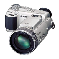
DIGITAL STILL CAMERA
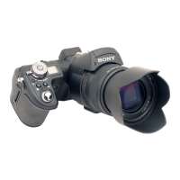
Photo: DSC-FX77
Question and Answer IconNeed help?

Do you have a question about the Sony DSC-F77 and is the answer not in the manual?

Sony DSC-F77 Specifications

General IconGeneral
Image SensorCCD
Max resolution2272 x 1704
Optical zoom3x
Digital Zoom2x
Focal Length7.9 - 23.7 mm
LensCarl Zeiss Vario-Tessar
LCD Screen Size1.5 inches
ISO SensitivityAuto, 100, 200, 400
StorageMemory Stick
Camera typeCompact
Video Recording320 x 240
Battery TypeLithium-ion
Optical Sensor Resolution4.1 megapixels

Summary

Service Notes and Safety Precautions

Repair Handling and Safety Guidelines

Guidelines for safe handling of cables, connectors, and capacitor discharging during repairs.

Self-Diagnosis Display Information

Explains camera self-diagnosis codes and countermeasures for error conditions.

Camera Disassembly Procedures

Hinge Cover Removal

Procedures for removing the hinge cover assembly for DSC-F77 and DSC-FX77 models.

Front Cabinet Disassembly

Steps for removing the front cabinet, including lid and main casing parts.

Internal Component Access

Procedures for accessing internal components like the control switch block and cabinet bottom.

Board and Flexible Circuit Locations

Identifies the location of main circuit boards and flexible circuit boards within the camera.

System Block Diagrams

Overall System Block Diagram

Illustrates the main functional blocks and signal paths within the camera system.

Power System Block Diagram

Details the power supply distribution and regulation within the camera.

Circuit Schematics and Wiring

Frame Schematic Diagram

Provides a high-level overview of the camera's internal connections and component layout.

CD-415 Board Schematics

Detailed circuit diagram for the CD-415 board, responsible for CCD imaging.

Waveform Analysis

Displays typical signal waveforms for the CD-415 board for diagnostic purposes.

Repair Parts List

Exploded Views - Camera Assemblies

Illustrates the overall assembly of DSC-F77 and DSC-FX77 models with part references.

Exploded Views - Component Assemblies

Detailed exploded views of specific assemblies like the lens cabinet.

Electrical Parts List Index

Index to electrical parts lists for various boards, including CD-415 and ST-78.

Related product manuals