DSC-TX20_L2
2-3
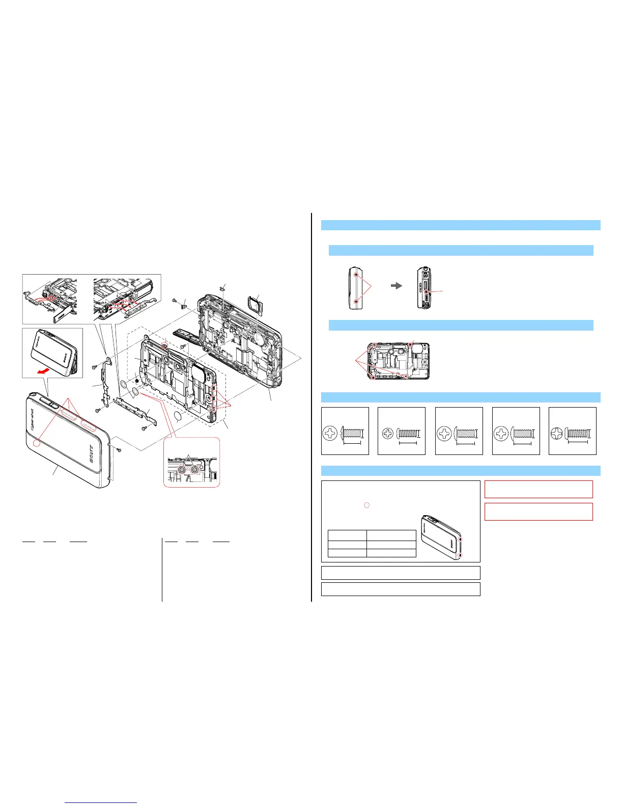
2-1. EXPLODED VIEWS
2-1-1. FRONT SECTION
ns: not supplied
Ref. No. Part No. Description
Ref. No. Part No. Description
1 X-2584-031-1 COVER ASSY (220) (BLACK), LENS (BLACK)
1 X-2584-032-1 COVER ASSY (220) (RED), LENS (PINK)
1 X-2584-033-1 COVER ASSY (220) (BLUE), LENS (BLUE)
1 X-2584-034-1 COVER ASSY (220) (GREEN),LENS (GREEN)
1 X-2584-035-1 COVER ASSY (220) (ORANG), LENS (ORANGE)
2 4-275-770-01 CONCLUDE (ML), PLATE (Note 2)
3 4-275-769-01 CONCLUDE (BT), PLATE
4 4-275-783-01 MICROPHONE, SHEET
5 4-179-356-01 INSPECTION, WATER SHEET
6 A-1884-093-A CABINET (FRONT) BLOCK ASSY
7 4-275-764-01 CONNECTOR, CONDUCTIVE
8 4-275-768-01 CONCLUDE (LC_G), PLATE
9 4-275-782-11 GUIDE (LOWER), LIGHT
10 4-275-778-01 LENS, CUSHION
#178 4-179-031-11 SCREW (M1.4) TRU-STAR SILVER (Note 3)
#180 4-179-319-01 TAPPING (1.7)
#222 4-284-334-11 SCREW (M1.4) TRU-STAR SILVER (Note 1)
#223 4-284-335-01 SCREW (M1.4) TRU-STAR BLACK (Note 1)
#224 4-284-396-01 TAPPING (1.4)
1. Remove to numerical order (1to 2) in the left figure.
DISASSEMBLY
1 #222 / #223 X 2 → #224 X 1 → Plate Conclude (LC_G)(1)
Be sure not to touch the A part
of the microphone sheet.
5
#222
#223
(Note 1)
ns
#178
(Note 3)
#178
(Note 3)
#180
#224
2
2
1
(Claws)
(Claws)
(Claw)
2
(Note 2)
2-1
8
1
10
9
1 1
2 6
Lens Section
(See page 2-4)
A part
#178
(Note 3)
3
2
-2
4
7
ns
#224
#222
#223
Right View Left View
Screw
Note
Screw's
Ref. No. (Parts Color.)
Cabinet's Color
Tabl e 2-1
Note 1
THE COMBINATION OF CABINET’S
COLOR AND SCREW
The screw pointed is different according to the cabinet's color.
For the combination of cabinet's color and screw, please refer
to Tabl e 2-1.
#222 (Silver)
BLACK / BLUE / ORANGE
#223 (Black)
PINK / GREEN
Note 2: When remove and install the plate conclude (ML), be careful not to be break
the conductive connector.
Note 2: Plate conclude (ML) を取り外し、取り付けをする際は、
conductive connector を破損させないよう注意してください。
3.0
1.4
#178: M1.4 X 3.0
(Silver)
4-179-031-11
5.0
1.7
#180:
M1.7 X 5.0 (Tapping)
(Silver)
4-179-319-01
#222:
3.0
1.4
M1.4 X 3.0
(Silver)
4-284-334-01
#223:
3.0
1.4
M1.4 X 3.0
(Black)
4-284-335-01
#224:
1.4
3.5
M1.4 X 3.5 (Tapping)
(Silver)
4-284-396-01
2 #178 X 3 → Plate Conclude (ML)(2-1)/Plate Conclude (BT)(2-2) → #180 X 1
#180
#178
Front View
Note 3: This screw cannot be re-used.
Discard the screw removed once in servicing.
Instead, use a new screw.
Note 3:
このねじは再利用することができません。
サービス対応時に一度でも外した場合は新品
のねじと交換してください。
 Loading...