DSC-TX20_L2
2-4
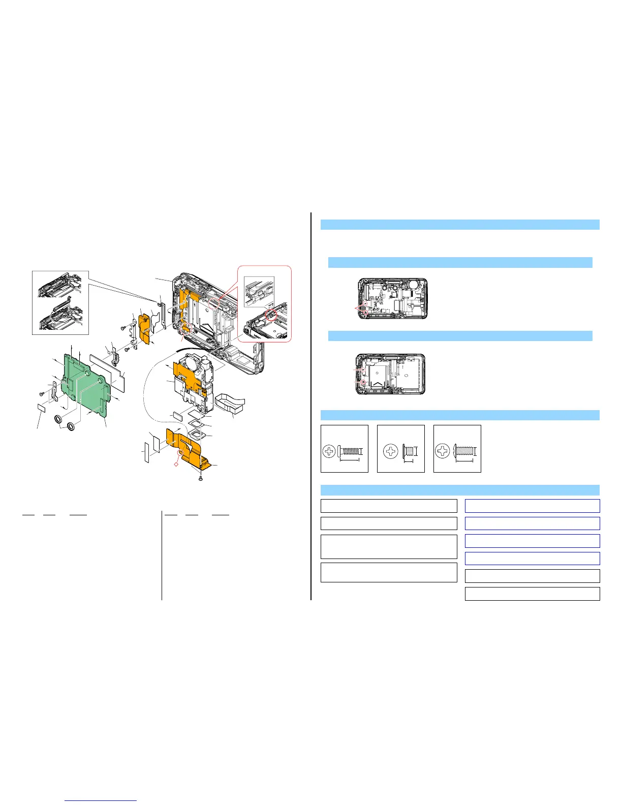
2-1-2. LENS SECTION
Ref. No. Part No. Description
Ref. No. Part No. Description
51 A-1871-517-A SY-333 BOARD, COMPLETE (SERVICE)
52 4-275-779-01 MICROPHONE, CUSHION
53 CAUTION SHEET (TP), FLEXIBLE PROTECTION
54 4-275-772-01 MULTI, PLATE
55 4-275-780-01 CUSHION (SY)
56 4-275-795-01 MULTI, ADHESIVE SHEET
57 4-275-774-01 MULTI, SOCKET
58 4-275-773-01 PLATE (HDMI)
59 A-1814-469-A HC-017 FLEXIBLE BOARD, COMPLETE
60 4-275-788-01 SHEET (HDMI), PROTECTION
61 4-275-775-01 SOCKET (HDMI)
62 A-1815-663-A LSV-1371B (SERVICE)
63 4-285-636-11 SHEET SP
64 4-275-793-11 CUSHION (CD)
65 4-170-733-11 SHEET, LENS LIGHT INTERCEPTION (Note 3)
66 1-856-058-11 OPTICAL FILTERBLOCK (OFB-02-39) (Note 2)
67 4-153-629-01 RUBBER, SEAL
68 A-1871-437-A CD-843 FLEXIBLE BOARD, COMPLETE
(including CP101 (CMOS imager)) (Note 1)
69 4-421-253-01 CUSHION (B TO B) (220)
70 4-150-538-02 PLATE, C LIGHT INTERCEPTION
#30 3-086-156-11 SCREW B1.2
#82 3-272-251-01 SCREW (M1.4), HEAD PRECISION
#160 4-139-851-01 SCREW (M1.4) TRU-STAR
DISASSEMBLY
53
(SIZE : 4.5mm X 6.8mm)
SY-333
52
57
56
60
66
70
(Note 2)
67
64
69
68
G
F
E
A
B
B
D
D
C
A
C
F
65
(Note 3)
#30
#160
#160
#82
(Note 4)
1 51
3 58
4 59
5 61
2 62
BTH Section
(See page 2-5)
1-1
54
1
-2
Be sure not to touch this part.
High voltage part
63
G
E
55
Note
1. Remove to numerical order (1to 5) in the left figure.
2. The meaning of the sign in left figure is as follows. Be careful when it removes.
◇-X: Solder
1 Flexible Protection Sheet (TP) (1-1) → #160 X 2 → Plate Multi (1-2)
#160
Front View
Screw
#30: M1.2 X 3.5 (Tapping)
(White)
3-086-156-11
3.5
1.2
#82: M1.4 X 1.4
(Silver)
3-272-251-01
1.4
1.4
3.0
1.4
#160: M1.4 X 3.0
(Silver)
4-139-851-01
3 #160 X 1 → #82 X 1
#82
#160
Front View
Note 1: Be sure to read “Precautions for Replacement of Imager” on
page 6-1 of Level 3 when changing the imager
Note 1:
イメージャの交換時は Level3 の 6-1 ページ、
“
イメージャ交換
時の注意
”
を必ずお読みください。
Note 2: Refer to “Assembly-1: How to distinguish the side of Optical Filter
Block facing to Lens Device.”.
Note 2:
“
Assembly-1: How to distinguish the side of Optical Filter
Block facing to Lens Device
”
を参照してください。
Note 3: Refer to “Assembly-2: Installation Cautions of Lens Light
Interception Sheet.”.
Note 3:
“
Assembly-2: Installation Cautions of Lens Light Interception
Sheet
”
を参照してください。
Note 4: When the flexible cable of the touch panel is connected or
disconnected, perform “Touch panel adj”.
Note 4:
タッチパネル部のフレキを抜き差しした場合は
,
タッチパネル
調整を実施すること。
CAUTION
For the part of 53 : SHEET (TP), FLEXIBLE PROTECTION (4-275-787-
03), cut POLYESTER TAPE (BLACK) 10 MM (9-913-210-03) into the
desired length and use it.
注意
53:SHEET(TP),FLEXIBLEPROTECTION(4-275-787-03)は、POLYESTER
TAPE(BLACK)10MM(9-913-210-03)を切って使用すること。
 Loading...