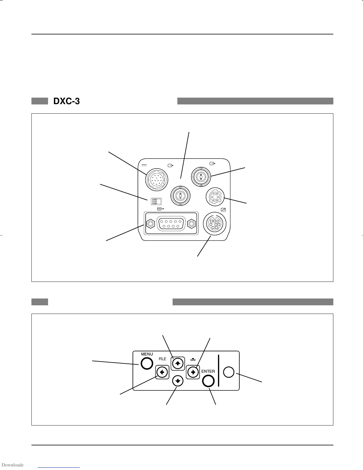
5. Camera Connectors
20
–
DXC-990/990P, DXC-390/390P Sales Manual
DC IN/ VBS
TRIG IN
VIDEO OUT
LENS
REMOTE
RGB/SYNC
ONOFF
MENU LOCK
MENU
FILE
SELECT
BLACK
WHITE
ENTER
BARS
DXC-390/390P REAR PANEL
DXC-390/390P SIDE PANEL
•DC IN/VBS OUT connector (12-pin)
Connects to the CMA-D2/D2CE Series
camera adaptor. DC power input and video
signal output.
•MENU LOCK switch
Mechanical switch protects
user settings. If this switch is ON,
buttons on side panel are disabled.
•RGB/SYNC connector
(D-sub 9-pin)
RGB signals and their respective sync
signals are output. CCMC-9DS/CCXC-9DBS
cable for the connections are used.
•REMOTE connector (mini-DIN 8-pin)
Connects to the RM-C950 remote control unit.
•LENS connector (6-pin)
Connects to a general lens with
video servo auto iris or the optional
VCL-610WEA/VCL-614WEA zoom
lens.
•VIDEO OUT connector (BNC)
Outputs (composite) video signals
from the camera.
•TRIG IN connector (BNC)
External trigger signal input when the camera is in the
strobe mode.
•MENU button
Displays/hides the menu on the
monitor screen.
•LEFT/FILE SELECT button
Decreases the settings values.
•DOWN button
Moves the cursor down.
•ENTER button
•BARS button
Displays/hides color bars.
•RIGHT/WHITE button
Increases the settings values.
•UP/BLACK button
Moves the cursor up.
DXC_990/390.qxp 01.3.2 3:46 PM Page 20
 Loading...