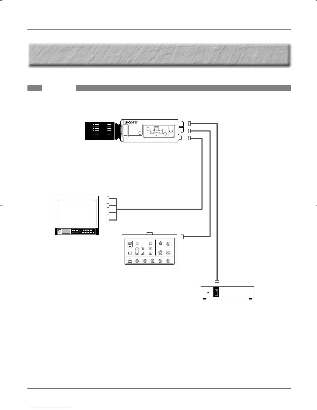
9. System Examples
30
–
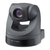
DXC-990/990P, DXC-390/390P Sales Manual
9. SYSTEM EXAMPLES
Note 1)
When using the CCDC cable between the DXC-990/990P/390/390P and the CMA-D2 Series, it is not possible to
output a video signal or input Genlock from the CMA-D2 Series.
Note 2)
When connecting the
DXC-990/990P/390/390P
over a 12-pin multi-core cable, it is not necessary to set the MODE
switch from 1 to 2.
Note 3)
Y/C signal can be output from the CMA-D2 Series. However, in this case, both Y/C and VBS signals can not be
output simultaneously. Each one should be selected according to the users requirement. When cables are
connected with both connectors (Y/C and VBS), the output signal from the VBS connector becomes B/W because
only the Y signal is output.
BASIC
Monitor
CCMC-9DS (4 BNC & S)
CCXC-9DBS (5 BNC)
CCDC-5 (5 m)
CCDC-10 (10 m)
CCDC-25 (25 m)
CCDC-A50 (50 m)
CCDC-A100 (100 m)
CCMC-12P02 (2 m)
CCMC-12P05 (5 m)
CCMC-12P10 (10 m)
CCMC-12P25 (25 m)
CMA-D2/D2CE
CMA-D2MD/D2MDCE
DXC-990/990P
DXC-390/390P
RM-C950
DXC_990/390.qxp 01.3.2 3:46 PM Page 30
 Loading...