Do you have a question about the Sony Handycam CCD-TR412E and is the answer not in the manual?
| Sensor Type | CCD |
|---|---|
| Recording Media | 8mm Video Cassette |
| Display | 2.5-inch LCD |
| Viewfinder | Electronic |
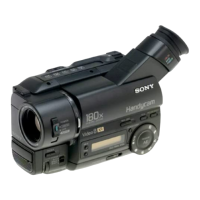
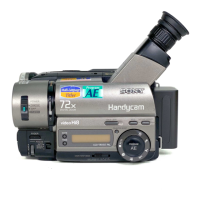
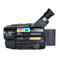
| Type | Analog Camcorder |
| Weight | 800g (with battery) |
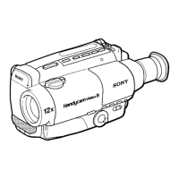
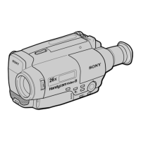
Details about the camera's zoom lens, including optical and digital zoom capabilities.
Lists the available input and output ports for audio, video, and data signals.
Lists critical safety checks to perform after repairs before releasing the unit to the customer.
Highlights critical components that require specific replacement parts for safe operation.
Describes the viewfinder display for error codes, indicating repair status and problem details.
Lists error codes, their symptoms, and corresponding correction procedures for troubleshooting.
Detailed procedures for calibrating camera functions like white balance and color reproduction.
Guides for adjusting mechanical aspects such as tape path and component alignment.
Step-by-step instructions for fine-tuning video signal parameters and performance.
Instructions on how to install and charge the camcorder's battery pack for operation.
Explains the basic steps and settings for recording video using the camcorder.
Details how to play back recorded tapes on the camcorder or connect to external devices.
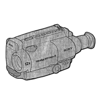
Illustrates and labels the various external and internal components of the camcorder.
Step-by-step guide for safely removing the front panel assembly of the camcorder.
Shows the physical placement of various circuit boards within the camcorder for service.
Presents a high-level overview of the camcorder's internal system architecture and signal flow.
Illustrates the signal paths and components within the camera and video processing sections.
Detailed wiring diagram for the VC-195 circuit board, showing component layout and connections.
Printed wiring board layout and schematic for the CF-49 control board.
Detailed procedures for calibrating camera functions like white balance and color reproduction.
Guides for adjusting mechanical aspects such as tape path and component alignment.
Step-by-step instructions for fine-tuning video signal parameters and performance.
Visual breakdown of the camcorder's parts with reference numbers for easy identification.
Comprehensive list of all electrical components, including part numbers and specifications.