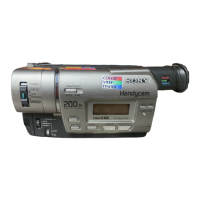
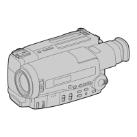
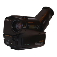
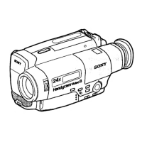
Do you have a question about the Sony Handycam CCD-TR57 and is the answer not in the manual?
Details on the camcorder's recording system, heads, and scanning.
Focal distance range for different models and conversion to 35mm camera.
List of available input and output terminals and their specifications.
Details on power requirements, operating temperature, dimensions, and mass.
Methods to prevent power shut-off during repairs for continuous operation.
Procedure for removing a cassette when the eject function is not working.
Overview of the self-diagnosis function for displaying operational issues.
Explanation of the 4-digit display indicating repair status, block, and error codes.
Procedure for accessing and viewing past self-diagnosis codes.
List of error codes, symptoms, and corresponding correction procedures.
Step-by-step guide for removing the front panel and video light assembly.
Procedure for removing the right cabinet assembly of the camcorder.
Steps for removing the first part of the Electronic Viewfinder block.
Guide for removing the TR cover, CF-49 board, and LCD block.
Procedure for removing the LB-54, VF-119, and VF-120 boards.
Steps for removing the battery panel assembly from the unit.
Procedure for removing the cassette lid assembly.
Procedure for removing the left cabinet assembly of the camcorder.
Steps for removing the control switch block assembly.
Procedure for removing the zoom lens block and VL-16 board.
Steps for removing the DD-105 and PJ-81 circuit boards.
Procedure for removing the VC-195 and SE-65 circuit boards.
Instructions for connecting parts for service procedures.
Diagrams showing the placement of various circuit boards within the camcorder.
A comprehensive block diagram illustrating the camcorder's main functional units.
Block diagram detailing the camera and video signal processing path.
Block diagram for the VTR and camera control systems.
Block diagram illustrating the servo system's control mechanisms.
Block diagram for the unit's mode control functions.
Block diagram showing the audio signal processing path.
Block diagram for the Color Electronic Viewfinder system.
Block diagram illustrating the camcorder's power supply and distribution.
Overall schematic diagram of the camcorder's internal circuitry.
Detailed diagrams for various circuit boards including component layouts.
Initial setup and precautions before performing camera adjustments.
General precautions, switch settings, and subject preparation for adjustments.
Step-by-step guide for performing camera adjustments in sequence.
Instructions for preparing the color bar chart and other subjects for adjustment.
How to use the remote commander for accessing adjustment menus and data.
Warnings and recommendations for proper use to avoid data loss.
Procedure to initialize or reset specific data pages in the camcorder.
Procedures for adjusting and checking the camcorder's mechanical sections.
Procedure to operate the mechanical deck without a cassette loaded.
Steps for adjusting the tape path for proper tape travel and tracking.
Procedures for adjusting video signal levels and characteristics.
List of instruments and initial setup for video section adjustments.
Information on accessing and using the service mode for adjustments.
The specified order for performing various video system adjustments.






 Loading...