Do you have a question about the Sony HCD-H1000 and is the answer not in the manual?
Details about the FM/AM superheterodyne tuner specifications.
Output power, input sensitivity, and impedance specifications for the amplifier.
Precautions for handling the optical pick-up block to prevent electrostatic breakdown.
Guidelines for safely checking the laser diode emission from the optical pick-up.
Procedure to check laser diode operation and objective lens movement.
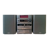
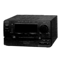
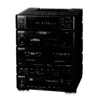
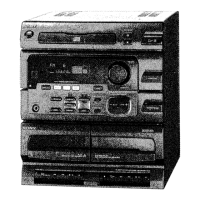
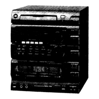
Identification of front panel, tuner, amplifier, and deck section parts and buttons.
Procedure for removing the outer case of the unit.
Steps to remove the power supply and transformer blocks.
Instructions for removing the main board from the unit.
Procedure to detach the CD mechanism block.
Steps for removing the tape cassette mechanism block.
Electrical adjustments for the tape deck, including torque and head azimuth.
Electrical adjustments for the tuner section, including FM and AM tuning.
Electrical adjustments for the CD player section, including S-curve and RF level checks.
Pin functions for the deck controller IC.
Diagrams showing the physical location of various circuit boards within the unit.
Pinout diagrams for various semiconductor components used in the unit.
Block diagram illustrating the signal flow and components of the CD section.
Block diagram showing the signal path and components of the tape deck section.
Block diagram detailing the main section's circuitry and interconnections.
Printed wiring board layouts for the main section of the unit.
Schematic diagram for the main section, detailing electronic components and connections.
Schematic diagram illustrating the circuitry of the tape deck section.
Printed wiring board layouts for the tape deck section of the unit.
Printed wiring board layouts for the CD section of the unit.
Schematic diagram detailing the electronic components and connections within the CD section.
Schematic diagram for the display section, showing its circuitry and connections.
Printed wiring board layouts for the display section of the unit.
Exploded view of the unit's case and power supply components.
Exploded view showing the parts and assembly of the front panel.
Exploded view of the tape mechanism deck chassis and its components.
Exploded view of the first part of the tape mechanism deck assembly.
Exploded view detailing the second part of the tape mechanism deck assembly.
Exploded view of the first part of the CD mechanism deck (CDM13B-5BD4E).
Exploded view of the second part of the CD mechanism deck (BU-5BD4E).
Electrical parts list for the AC board (A).
Electrical parts list for the BD board's display section.
Electrical parts list for display and jack components.
Electrical parts list for TC, Transformer (A/B), and VOL sections.
Electrical parts list for the Power Supply section.
Electrical parts list for Power Supply switches.
Electrical parts list for MD-BX, Microphone, and Power sections.
Electrical parts list for SW boards and TC section.
Electrical parts list for the MD board.
| CD Player | Yes |
|---|---|
| Bluetooth | No |
| USB Port | No |
| Remote Control | Yes |
| Audio Channels | 2.0 |
| Radio Tuner | AM/FM |
| Cassette Deck | Yes |
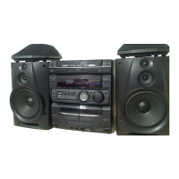
| Speakers | 2 |