EasyManua.ls Logo

Sony HDR-CX170 User Manual

Sony HDR-CX170
33 pages
To Next Page IconTo Next Page
Page #1 background imageLoading...
Page #1 background image
Sony EMCS Co.
Revision History
Ver. Date History Contents
DCR-SX73E/SX83/SX83E, HDR-CX110/CX110E/CX115E/CX116E/CX150/CX150E/CX155E/CX170_L3
SERVICE MANUAL
985275811.pdf
2010A0800-1
© 2010.01
Published by Tokai TEC
The components identified
by mark 0 or dotted line with
mark 0 are critical for safety.
Replace only with part number
specified.
Les composants identifiés par une
marque 0 sont critiques pour la
sécurité.
Ne les remplacer que par une
pièce portant le numéro spécifié.
Official Release2010.011.0
9-852-758-11
Ver. 1.0 2010.01
LEVEL 3
Check the SERVICE NOTE (LEVEL 2) before the service.
US Model
Canadian Model
AEP Model
UK Model
North European Model
E Model
Australian Model
Hong Kong Model
Chinese Model
Korea Model
Brazilian Model
Tourist Model
Japanese Model
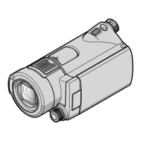
Photo: HDR-CX150/BLACK
DCR-SX73E/SX83/SX83E
DIGITAL VIDEO CAMERA RECORDER
HDR-CX110/CX110E/CX115E/CX116E/CX150/CX150E/CX155E/CX170
DIGITAL HD VIDEO CAMERA RECORDER
DCR-SX73E/SX83/SX83E
HDR-CX110/CX110E/CX115E/CX116E/
CX150/CX150E/CX155E/CX170
Question and Answer IconNeed help?

Do you have a question about the Sony HDR-CX170 and is the answer not in the manual?

Sony HDR-CX170 Specifications

General IconGeneral
BrandSony
ModelHDR-CX170
CategoryCamcorder
LanguageEnglish

Summary

SERVICE MANUAL

Revision History

Details the changes and updates made to the service manual over time.

Service Notes and Model Variations

Highlights critical service notes and lists different model variations covered by the manual.

Safety Related Component Warnings

Component Identification for Safety

Identifies components critical for safety operation, marked with specific symbols.

General Safety Precautions

Provides essential cautions regarding battery handling and general safety practices during service.

Unleaded Solder Information

Details the characteristics and handling of unleaded solder used in the device.

Repair Parts List

Component Safety Warnings

Identifies components critical for safety operation and provides related warnings.

Safety Precautions for Component Replacement

Details critical safety components and provides general precautions for part replacement procedures.

Schematic Diagrams and Printed Wiring Boards

Schematic Diagram Conventions

Explains symbols and notations used in schematic diagrams, including component identification.

Printed Wiring Board Conventions

Details the conventions and markings used on printed wiring boards for clarity.

Imager Replacement Precautions

Provides specific instructions and warnings for replacing the imager component.

Component Safety Markings

Explains the meaning of safety marks (▲) and dotted lines used to identify critical components.

Printed Wiring Boards Overview

CM-114 Board Layouts

Illustrates the physical layout of the CM-114 board, showing component placement on both sides.

JK-395 Board Layouts

Presents the physical layout of the JK-395 board, detailing component placement on both sides.

VC-590 Board (Side A) Layout

VC-590 Board (Side B) Layout

MS-431 Board Layouts

MS-431 Board (Side A) Component Placement

Shows the component layout on Side A of the MS-431 board, including connectors and key parts.

MS-431 Board (Side B) Component Placement

Details the component layout on Side B of the MS-431 board, highlighting battery holder and sensor locations.

Lithium Ion Battery Replacement Note

Provides specific instructions for replacing the lithium ion battery and its holder on the MS-431 board.

Related product manuals