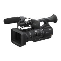
Do you have a question about the Sony HVR-Z5C and is the answer not in the manual?
| Sensor Size | 1/3 inch |
|---|---|
| Lens | Carl Zeiss Vario-Sonnar T* |
| Optical Zoom | 20x |
| Focus System | Auto/Manual |
| Battery | NP-F570 |
| Type | Professional Camcorder |
| Maximum Aperture | f1.6-2.8 |
| LCD Screen | 3.2" LCD |
| Viewfinder | 0.45 inch LCD |
| Recording Media | Memory Stick PRO Duo |
| Recording Format | HDV, DV |
| Video Resolution | 1080i |
| Video Signal | PAL |
| Audio Recording | Stereo |
| Audio Input | XLR input |
| Input/Output | HDMI, Component, USB |
| Shutter Speed | 1/3 - 1/10, 000 sec |
| Weight | Approx. 2.2 kg (with battery) |
| Focal Length | 4.1-82mm (35mm equivalent: 32.5-650mm) |
Details the video recording, still image, and audio recording systems.
Lists the available video, audio, and data output connectors.
Provides general specifications including power requirements, operating temperature, and dimensions.
Details the specifications for the AC adapter/charger, including power requirements and dimensions.
Lists the specifications for the rechargeable battery pack, including voltage, capacity, and type.
Details characteristics and precautions for using unleaded solder.
Explains how to supply power to the unit during repairs to prevent automatic shutdown.
Provides a procedure to eject a cassette that is not ejecting normally.
Details the procedure to force the camcorder power ON using the adjustment remote commander.
Explains how the self-diagnosis function operates and displays information.
Describes the 4-digit display format indicating repair status, block, and detailed codes.
Provides important notes for repair procedures, including handling flexible boards and cables.
Offers guidance on safely disconnecting the coaxial cable harness.
Illustrates the overall functional blocks of the camcorder.
Details the power block diagram of the camcorder.
Provides schematic diagrams for the VC-543 board, detailing various sections.
Offers schematic diagrams for the CM-097 board, related to the CMOS imager.
Provides schematic diagrams for the MD-141 board, covering motor drive and amplifier circuits.
Provides instructions on how to mount the accessory shoe onto the camcorder.
Provides instructions on how to remove the accessory shoe from the camcorder.
Provides exploded views of the camcorder sections for parts identification.
Lists electrical parts, mapping them to exploded view sections.
Covers essential preparatory steps, including EVR data re-writing and initializations.
Details procedures for adjusting camera-related functions like white balance, exposure, and iris.
Provides instructions for cleaning, inspecting, and adjusting mechanical parts.
Outlines procedures for adjusting video signal levels and color reproduction.
Details system-level adjustments, including EEPROM initialization and serial number input.
Provides instructions for adjusting servo and RF systems, including CAP FG duty.
Explains the operation of adjustment tools like the remote commander and service mode.
 Loading...