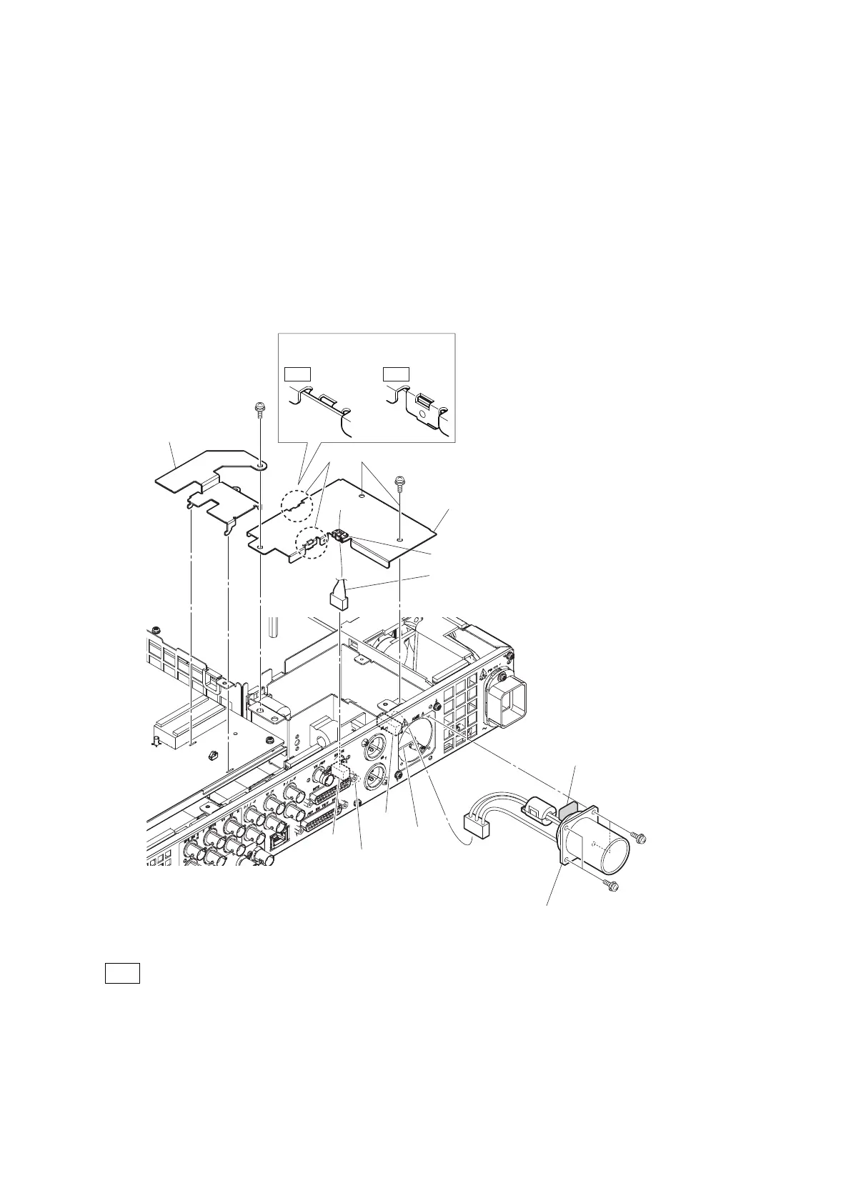
4-7. TRIAX Connector Assembly
Preparation
1. Remove the top cover. (Refer to “4-2. Top Cover”)
Procedure
1. Open the locking edge saddle and disconnect the harness from the connector (CN014) on the CN-3662 board.
2. Remove the screw to detach the DM shield plate.
3. Remove the two screws to detach the FL cover.
4. Disconnect the harness from the connector (CN001) on the FL-378 board.
5. Remove the four screws to detach the TRIAX connector assembly.
OK NG
TRIAX connector assembly
(Illustration: UC connector)
Capacitor
FL-378 board
CN-3662 board
CN014
CN001
FL cover
Locking edge saddle
Harness
PSW3 x 6
Note for installation
PSW3 x 6
PSW3 x 6
PSW3 x 6
DM shield plate
Claws
Tip
• When installing the TRIAX connector assembly, carefully install it paying attention to the capacitor shown in
the figure.
• Attach two claws of the FL cover as shown in the figure.
6. Install the removed parts by reversing the steps of removal.
HXCU-TX70
4-11
 Loading...