EasyManua.ls Logo

Sony ICF-SW7600GR - Portable Radio User Manual

Sony ICF-SW7600GR - Portable Radio
26 pages
To Next Page IconTo Next Page
Page #1 background imageLoading...
Page #1 background image
ICF-SW7600GR
US Model
Canadian Model
AEP Model
Chinese Model
E Model
Tourist Model
SERVICE MANUAL
FM STEREO/SW/MW/LW
PLL SYNTHESIZED RECEIVER
Sony Corporation
Audio Entertainment Group
General Engineering Dept.
SPECIFICATIONS
Ver 1.0 2001. 03
9-873-099-11
2001C1600-1
© 2001.3
Circuit system FM: Super heterodyne
AM: Dual conversion super heterodyne
Frequency range FM: 76–108 MHz
SW: 1 621– 29 999 kHz
MW: 530–1 620 kHz
LW: 150–529 kHz
Output LINE OUT jack (stereo minijack) × 1
Recording output level approx. 245 mV, output
impedance less than 10 k
i (headphones) jack (stereo minijack) × 1 16
Speaker Approx. 77 mm diameter, 8 × 1
Maximum output 380 mW (at 10 % harmonic distortion)
Power requirements DC 6 V, four R6 (size AA) batteries
External power source DC IN 6V (except Chinese)
Dimensions Approx. 190 × 118.8 × 35.3 mm incl. projecting parts
(w/h/d)
Mass Approx. 536 g
Approx. 608 g (incl. four R6 (size AA) batteries)
Supplied accessories
Carrying case (1)
Compact antenna AN-71 (1)
Wave Handbook (1)
Design and specifications are subject to change without notice.
Question and Answer IconNeed help?

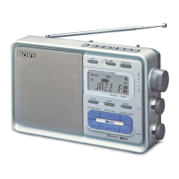
Do you have a question about the Sony ICF-SW7600GR - Portable Radio and is the answer not in the manual?
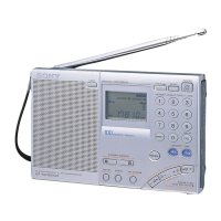
Sony ICF-SW7600GR - Portable Radio Specifications

General IconGeneral
ManufacturerSony
ModelICF-SW7600GR
DisplayLCD
TypePortable Radio
Power Source4 AA batteries or AC adapter
FeaturesSSB reception
Tuning ModesManual, Scan, Preset
AntennaTelescopic antenna for FM/SW, built-in ferrite bar antenna for LW/MW
SpeakerBuilt-in
Headphone Jack3.5 mm
Tuning StepsFM: 0.05 MHz, SW: 1 kHz, MW: 9/10 kHz, LW: 9 kHz
Weight617 g (1 lb 6 oz) including batteries

Summary

Operating Controls and Display Indicators

Control Panel Layout

Identifies and describes the function of each button on the control panel.

Display Indicators and Functions

Explains the meaning and function of various indicators shown on the receiver's display.

Setting the Current Time

Electrical Adjustments

VCO and IF Adjustments

Procedures for VCO and 1st IF adjustments for optimal receiver performance.

2nd Local and Tracking Adjustments

Procedures for 2nd local and FM tracking adjustments for optimal signal reception.

76kHz, Just Tune, and SSB Adjustments

Procedures for 76kHz (MPX), Just Tune, and SSB 0 Beat adjustments.

System Block Diagrams

Printed Wiring Boards

Schematic Diagrams

Integrated Circuit (IC) Information

IC Pin Function Descriptions

Details the pin functions and descriptions for key integrated circuits used in the receiver.

Electrical Parts List

Related product manuals