EasyManua.ls Logo

Sony ICF-111B User Manual

Sony ICF-111B
15 pages
To Next Page IconTo Next Page
Page #1 background imageLoading...
Page #1 background image
~
PORTABLE
RADIO.
SPECIFICATIONS
Circuit
System:
10-transistor,
1-FET,
1-1C,
5-diode
Current
Drain
superheterodyne
.
at
zero
signal:
FM
36mA,
SW/MW
30mA
1-transistor,
1-diode,
1-LED
for
at
10%
distortion:
370
mA
auxiliary
circuit
Power
Requirement:
Three
‘‘C”’
size
flashlight
batteries
Frequency
Coverage:
FM
87.5~
108
MHz
(3.42~2.78
m)
4.5V
in
total
SW
3.9
~12MHz
(77
~
25m)
Car
battery
can
be
used
with
MW
530
~
1,605
kHz
(566
~
187m)
SONY
DCC-126
Car
Battery
Cord
(option).
House
current
can
be
used
with
SONY
AC-90E
AC
Power
Antenna
System:
FM/SW
built-in
telescopic
antenna
Adaptor
(option).
MN
BEI
G.
Terrie
ab
antenna
Speaker:
9.2cm
(3!4")
dia.
PM
dynamic,
82
Intermediate
Frequency:
FM
10.7MHz
SW/MW
455
kHz
Sensitivity
at
50
mW
output:.
FM
1.26uV
(2dB)
at
S/N
30dB
SW
1nuV
(OdB)
MW
16uV/m
(24
dB/m)
Weight:
1.3kg
(2lb
140z)
with
batteries
Dimensions:
214mm
(W)
x
178mm
(H)
x
56mm
(D)
(S7h6"
x
7”
x
26")
Selectivity
.
at
£10
kHz
off-resonance:
35dB
at
1,400kHz
Power
Output
at
10%
distortion:
700
mW
maximum:
1.1W
ONY.
SERVICE
MANUAL
Question and Answer IconNeed help?

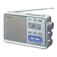
Do you have a question about the Sony ICF-111B and is the answer not in the manual?

Sony ICF-111B Specifications

General IconGeneral
BrandSony
ModelICF-111B
CategoryPortable Radio
LanguageEnglish

Summary

Specifications

SECTION 2 DISASSEMBLY

2-1. REAR CABINET REMOVAL

Procedure for removing the rear cabinet of the radio.

2-2. CHASSIS REMOVAL

Steps to remove the main chassis from the radio.

2-3. CIRCUIT BOARD REMOVAL

Instructions for removing internal circuit boards.

2-4. RESONANCE INDICATING CIRCUIT BOARD REMOVAL

Procedure for detaching the resonance indicating circuit board.

SECTION 3 CIRCUIT ADJUSTMENTS

3-1. FM IF ALIGNMENT

Steps and required equipment for FM Intermediate Frequency alignment.

3-2. AM IF ALIGNMENT

Procedure and tools for AM Intermediate Frequency alignment.

3-3. FREQUENCY COVERAGE AND TRACKING ADJUSTMENT

Adjusting radio frequency coverage and tracking for FM and AM.

3-4. CURRENT ADJUSTMENT

Procedure for adjusting the radio's current draw.

SECTION 4 SCHEMATIC AND MOUNTING DIAGRAMS

4-1. SCHEMATIC DIAGRAM

Detailed electronic schematic of the radio's circuitry.

4-2. MOUNTING DIAGRAM

Diagram showing component mounting locations on the circuit board.

SECTION 5 EXPLODED VIEW AND PACKING

5-1. EXPLODED VIEW (1)

First part of the exploded diagram showing radio components.

5-2. EXPLODED VIEW (2)

Second part of the exploded diagram detailing radio components.

SECTION 6 ELECTRICAL PARTS LIST

Hardware Nomenclature

Related product manuals