Do you have a question about the Sony KDL-26T3000 and is the answer not in the manual?
Technical specifications of the product.
Description of input and output connectors.
Details of rear input/output terminals.
General electrical and physical characteristics of the TV.
Details of side input/output terminals.
Step-by-step instructions for removing the rear cover.
Procedure for removing the television stand.
Details on performing electrical adjustments using the remote commander.
Accesses the digital service menu.
Overall block diagram of the system architecture.
Schematic diagrams and printed wiring board layouts.
Exploded view of the main chassis and its components.
Complete parts list for the U2 board for 32/40 inch models.
Complete parts list for the G3 board for 40 inch models.
Complete parts list for the D1 board for 40 inch models.
Common parts list for the BC board across all models.
Variant parts list for the BC board specific to models.
Complete parts list for the H2 board.
Complete parts list for the H1 board.
Common parts list for the G1 board for 26/32 inch models.
Variant parts list for the G1 board specific to models.
Complete parts list for the U1 board for 26 inch models.
Schematic diagram of the G1 power supply board, page 1A/1.
| Brand | Sony |
|---|---|
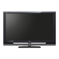
| Model | KDL-26T3000 |
| Category | Flat Panel TV |
| Language | English |