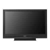
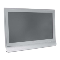
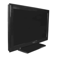
Do you have a question about the Sony KDL-26U4000 and is the answer not in the manual?
Information on the use of Lead Free Solder and required precautions for servicing.
Details on TV systems, channel coverage, and color/video systems.
Specs for picture size, sound output, power, dimensions, weight, other features.
Lists and describes all input and output connectors on the device.
Detailed pin assignments and signal descriptions for the SCART connector.
Critical safety instructions regarding the UK power plug.
Pin assignments and signal descriptions for HDMI and PC connectors.
Diagrams showing rear and side connection panel layouts.
Explains LED flash codes for error identification and recommended actions.
Instructions for removing rear cover, stand, loudspeaker, and side jack bracket.
Steps to remove the BC1, GA2, and GA3 circuit boards.
Instructions for removing the HM4 and HM5 circuit boards.
Step-by-step guide to access the TV's service adjustment menu.
Lists specific parameters adjustable within the service mode, like Backlight and HDMI settings.
Describes various "Test Mode" (TT) functions accessible via specific remote codes.
Details on how to use TT modes, including exiting the mode.
Explanation of on-screen display labels used in Test Mode and their meanings.
First part of the GA2 power supply circuit diagram.
Second part of the GA2 power supply circuit diagram.
First part of the GA3 power supply circuit diagram.
Second part of the GA3 power supply circuit diagram.
Layouts for BC1, GA2, and GA3 printed wiring boards.
Layouts for HM4 and HM5 printed wiring boards.
Diagram and list of main chassis components for disassembly.
Detailed list of parts for the TV chassis, with reference numbers.
Exploded view and part number for the bezel assembly.
Part numbers and descriptions for the bezel assembly components.
Exploded views and part numbers for rear covers and power supply cords.
Part numbers for rear covers and power supply cords for different models.
Comprehensive list of components for the BC1 board, organized by type across multiple pages.
List of components for the HM4 board, organized by type.
List of components for the HM5 board, organized by type.
List of components for the HM4 board, organized by type.
List of components for the HM5 board, organized by type.
Detailed list of diodes, ICs, transistors, and resistors for the HM4 board.
Detailed list of diodes, ICs, transistors, and resistors for the HM5 board.
List of accessories, connectors, and lead wires with part numbers.
Details about the specific remote commander model (RM-ED009).
| Screen Size | 26 inches |
|---|---|
| Resolution | 1366 x 768 |
| Display Type | LCD |
| HD Format | 720p |
| HDMI Ports | 2 |
| USB Ports | 1 |
| Refresh Rate | 50 Hz |
| Aspect Ratio | 16:9 |
| Sound Output | 10 W |
| Inputs | Composite |
