Do you have a question about the Sony KDL-32EX427 and is the answer not in the manual?
General warnings, handling, cleaning, and safety checks for servicing.
Instructions for connecting and disconnecting LVDS FFC connectors.
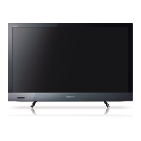
Details on the various features of the BRAVIA TV models.
Detailed technical specifications for the TV models.
Explains the reasons and procedures for updating TV software.
Outlines responsibilities for software updates between customers and servicers.
Guide on how to check the current software version on the TV.
Lists symptoms that can be resolved by software updates.
Introduces the AZ2-F chassis and lists primary circuit boards.
Detailed descriptions of individual circuit boards and their functions.
Provides block and connector diagrams for the chassis layout.
Introduces the troubleshooting chapter and software updates.
A chart to help diagnose potential causes of TV errors.
Explains protection shutdown and Standby LED flash count for diagnostics.
Provides descriptions and possible locations for diagnostic error codes.
Guides on viewing, clearing, and resetting diagnostic information.
Introduces flowcharts for troubleshooting various TV issues.
Detailed flowcharts for specific error conditions like No Power, Blinking LEDs.
Flowcharts for issues like No Picture, No Sound, button malfunctions.
Flowcharts for network connectivity and Skype accessory problems.
Step-by-step guides for disassembling and removing TV components.
Information on screws, connectors, and part numbers.
Details on included accessories, optional items, and remote commander.
Diagrams illustrating wire routing and management within the TV.
Introduction to service adjustments and accessing service mode.
Steps for updating service data after replacing main board, including code, destination, model.
Procedures for adding serial number and confirming model/product IDs.
Adjustments for LCD panel replacement, including BU Flash Data and operation time.
Steps for adjusting VCOM data to fix picture flickering issues.
Procedures for optional adjustments like white balance and resetting to factory condition.
Instructions for safely removing the power cord during rear cover removal.
Procedures for removing rear covers for KDL-40EX527 and KDL-46EX527 models.
Instructions for reattaching the rear cover to the TV bezel.
Procedures for attaching rear covers for KDL-40EX527 and KDL-46EX527 models.
Step-by-step guide for removing the LCD panel from the TV bezel.
Instructions for securely reattaching the LCD panel to the TV bezel.
Details the symptoms and potential causes of an 8-blink error code.
Provides steps to diagnose and resolve an 8-blink error code.
| Screen Size | 32 inches |
|---|---|
| Resolution | 1366 x 768 |
| Display Type | LCD |
| Backlight Type | LED |
| HDMI Ports | 4 |
| USB Ports | 2 |
| Wi-Fi | Yes |
| Display Resolution | 1366 x 768 |
| BRAVIA Engine | BRAVIA Engine 3 |
| Refresh Rate | 50 Hz |
| Smart TV | Yes |
| 3D Capable | No |
| Energy Efficiency Class | A |





 Loading...