EasyManua.ls Logo

Sony KDL-40W4100 User Manual

Sony KDL-40W4100
126 pages
To Next Page IconTo Next Page
Page #1 background imageLoading...
Page #1 background image
LCD DIGITAL COLOR TELEVISION
SERVICE MANUAL
EX1
CHASSIS
MODEL NAME REMOTE COMMANDER DESTINATION
9-883-779-01
KDL-40W4100
RM-YD023 US
KDL-40W4100
RM-YD023 CANADA
KDL-40W4100
RM-YD023 MEXICO
KDL-40W4100
RM-YD023 LATIN AMERICA
KDL-46W4100
RM-YD023 US
KDL-46W4100
RM-YD023 CANADA
KDL-46W4100
RM-YD023 MEXICO
KDL-46W4100
RM-YD023 LATIN AMERICA
KDL-46W4150
RM-YD023 US
KDL-46W4150
RM-YD023 CANADA
HISTORY INFORMATION FOR THE FOLLOWING MANUAL:
ORIGINAL MANUAL ISSUE DATE: 4/2008
REVISION DATE SUBJECT
4/2008 No revisions or updates are applicable at this time.

Table of Contents

Question and Answer IconNeed help?

Do you have a question about the Sony KDL-40W4100 and is the answer not in the manual?
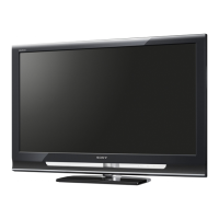
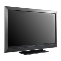
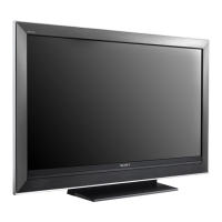
Sony KDL-40W4100 Specifications

General IconGeneral
Screen Size40 inches
Resolution1920 x 1080
Display TypeLCD
Backlight TypeCCFL
Brightness450 cd/m²
Response Time8 ms
Component Video Inputs2
Composite Video Inputs1
USB Ports1
Audio Output10W x 2
Weight24.2 kg
S-Video Input1
PC Input1
Refresh Rate60 Hz
Viewing Angle178°
Speakers2

Summary

HISTORY INFORMATION FOR THE FOLLOWING MANUAL

ORIGINAL MANUAL ISSUE DATE: 4/2008

Indicates the initial release date of the manual.

SPECIFICATIONS

WARNINGS AND CAUTIONS - ENGLISH

SAFETY-RELATED COMPONENT WARNING!!

Warning about critical safety components and replacement procedures.

USE CAUTION WHEN HANDLING THE LCD PANEL

Precautions for safely handling the LCD panel to avoid damage.

LEAKAGE CURRENT HOT CHECK CIRCUIT

Circuit diagram for checking leakage current.

SAFETY CHECK-OUT

Leakage Test

Procedure for testing AC leakage current.

How to Find a Good Earth Ground

Methods to verify a proper earth ground connection.

SELF-DIAGNOSTIC FUNCTION

1. Diagnostic Test Indicators

Explanation of STANDBY LED flash codes for error diagnosis.

Description of LED Indictors

Details on the meaning of POWER, STANDBY, and PIC OFF LEDs.

Viewing the Self Check Diagnostic List

How to display and interpret self-check diagnostic codes.

Clearing the Self Check Diagnostic List

Steps to clear the self-check diagnostic list.

SECTION 1: DISASSEMBLY

1-1. REAR COVER REMOVAL

Steps for removing the rear cover of the TV.

1-2. SWITCH UNIT REMOVAL

Procedure for removing the switch unit.

1-3. SIDE JACK BRACKET, BU SHIELD AND BU BOARD REMOVAL

Steps to remove side jack bracket, BU shield, and BU board.

1-4. POWER UNIT REMOVAL (IP5Z BOARD)

Instructions for removing the power unit.

1-5. STAND REMOVAL

Guide for removing the TV stand.

1-6. UNDER COVER AND AC INLET REMOVAL

Steps to remove under cover and AC inlet.

1-7. STRUCTURAL FRAMES AND BRACKETS REMOVAL (KDL-40W4100 ONLY)

Removing structural frames for KDL-40W4100.

1-8. STRUCTURAL FRAMES AND BRACKETS REMOVAL (KDL-46W4100/46W4150 ONLY)

Removing structural frames for KDL-46W4100/46W4150.

1-9 SPEAKERS, UNDER BAR, H3E/H4 BOARD AND LIGHT GUIDE REMOVAL

Steps to remove speakers, H3E/H4 board, and light guide.

1-10. LCD PANEL REMOVAL

Procedure for removing the LCD panel.

1-11. BALANCER (ETC-INVERTER MT) BOARD REMOVAL

Instructions for removing the balancer board.

WIRE DRESSING (KDL-40W4100 ONLY)

H Boards/Speaker Harness

Instructions for routing H boards and speaker harness.

Balancer Board Cable Routing

Guidelines for routing the balancer board cable.

LVDS Cable Routing

Instructions for routing the LVDS cable correctly.

WIRE DRESSING (KDL-46W4100/46W4150 ONLY)

H Boards/Speaker Harness

Instructions for routing H boards and speaker harness for 46W models.

Balancer Board Cable Routing

Guidelines for routing balancer board cable for 46W models.

LVDS Cable Routing

Instructions for routing LVDS cable for 46W models.

SECTION 2: SERVICE ADJUSTMENTS

2-1. VIEWING SERVICE ADJUSTMENT DATA

Information on viewing service adjustment data.

2-2. ACCESSING SERVICE ADJUSTMENT MODE

Steps to enter the service adjustment mode.

2-3. VIEWING THE SERVICE MENUS

How to navigate and view service menus.

2-4. USING THE REMOTE COMMANDER TO VIEW SERVICE DATA

Using the remote to view and adjust service data.

2-5. RESETTING TO FACTORY DEFAULTS

Procedure to restore factory default settings.

SECTION 3: DIAGRAMS

3-1. CIRCUIT BOARDS LOCATION

Diagram showing the location of circuit boards in the TV.

3-2. PRINTED WIRING BOARDS AND SCHEMATIC DIAGRAMS INFORMATION

Information on PWB and schematic diagram conventions.

3-3. BLOCK DIAGRAM

Overall system block diagram.

3-4. SCHEMATICS AND SUPPORTING INFORMATION

Detailed schematics for various boards and circuits.

3-5. SEMICONDUCTORS

List and identification of semiconductor components.

SECTION 4: EXPLODED VIEWS

4-1. REAR COVER ASSEMBLY AND STAND ASSEMBLY

Exploded view of rear cover and stand assembly.

4-2. CHASSIS

Exploded view of the TV chassis components.

4-3. CONNECTORS

Diagram showing various connectors and their part numbers.

4-4. BEZEL ASSEMBLY AND LCD PANEL (KDL-40W4100 ONLY)

Exploded view of bezel and LCD panel for KDL-40W4100.

4-5. BEZEL ASSEMBLY AND LCD PANEL (KDL-46W4100/46W4150 ONLY)

Exploded view of bezel and LCD panel for 46W models.

4-6. SCREW LEGEND

List of screws used in disassembly with quantities and locations.

SECTION 5: ELECTRICAL PARTS LIST

APPENDIX A: ENCRYPTION KEY COMPONENTS

Encryption key components handling and replacement

Guidelines for handling and replacing encryption key components.

Related product manuals