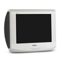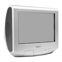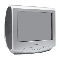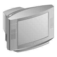
Do you have a question about the Sony KV-21LS30E and is the answer not in the manual?
| Screen Size | 21 inches |
|---|---|
| Display Technology | CRT |
| Aspect Ratio | 4:3 |
| Weight | 22 kg |
| TV System | PAL, SECAM |
| Remote Control | Yes |
| Input Ports | RF |
Identifies the specific chassis model FE-2 for the service manual.
Highlights the FD Trinitron technology used in the described TV models.
Details compatibility with various television broadcasting systems and color standards.
Lists key specifications including power, dimensions, weight, and sound output.
Provides a table outlining various selectable features for different models.
Specific safety instructions regarding fuse replacement for UK models.
Detailed pin assignment and signal description for the 21-pin connector.
Visual guide to the physical layout of the TV's rear and front connection panels.
Explains how to identify and interpret error messages via LED codes and NVM storage.
Step-by-step guide for turning on the TV and performing automatic channel tuning.
Instructions for selecting the menu language and operating country.
Procedures for adjusting picture slant and reordering TV channels.
Guide on using remote control buttons to navigate and operate the on-screen menu.
Details on adjusting various sound parameters like treble, bass, and balance.
Instructions for adjusting picture settings like contrast, brightness, and sharpness.
Configuration for automatic TV power on and off functions.
Guidance on RGB Centring and Picture Rotation for geometry correction.
Steps to select menu language and country settings.
Instructions on how to access and use the Teletext information service.
Guidance on connecting external devices like VCRs and DVD players.
Provides a summary of TV system, color system, and channel coverage.
Offers solutions for common picture and sound problems encountered with the TV.
Step-by-step instructions for removing the rear cover of the television set.
Guide on removing the speaker box and disassembling it for service.
Detailed steps for removing the A Board Printed Wiring Board (PWB).
Instructions for placing the board in a service position and managing wires.
Crucial safety warning regarding high voltage before removing the picture tube.
Procedure for safely handling and removing the anode cap from the CRT.
Lists the necessary test equipment for performing picture adjustments.
Step-by-step guide for adjusting beam landing using purity controls and magnets.
Preparation steps before starting convergence adjustment, including focus and size settings.
Procedure for adjusting horizontal and vertical static convergence using H.STAT and V.STAT.
Details on YCH, TLV, and HTIL adjustments for geometry correction.
Method for correcting screen corner convergence defects using permalloy magnets.
Steps to adjust the focus control on the flyback transformer for optimal sharpness.
Procedure for adjusting the G2 control to set the screen brightness and flyback return lines.
Guide for adjusting white balance using service mode and remote commander.
Instructions on how to access the TV's service mode using the remote commander.
Adjusting sub-brightness and sub-contrast levels within the service menu.
Procedures for adjusting sub colour levels and tuner automatic gain control (AGC).
Details on adjusting various geometry parameters for the deflection system.
Explanation of functions and key operations available in Test Mode 1.
Description of functions and key operations available in Test Mode 2.
Overview of the main functional blocks of the TV's circuitry.
Further block diagram illustrating system connections and components.
Identifies the physical placement of various circuit boards within the TV.
Detailed waveforms and voltage measurements for the CVM board.
Key for understanding resistor, capacitor, and other component markings in schematics.
Schematic diagram for specific sections of the A board (1/2).
Reference tables for semiconductor and IC voltages for troubleshooting.
Lists and images of various transistors and integrated circuits used in the TV.
Part numbers and identification for diodes and other semiconductor components.
Functional block diagrams for key integrated circuits used in the TV.
Diagram and list of components making up the TV's chassis assembly.
Diagram and list of components related to the picture tube and its assembly.
List of common capacitor part numbers for the A Board.
List of capacitor part numbers specific to A Board variants.
Part numbers for various diodes and connector components.
Part numbers for filters, integrated circuits, sockets, and coils.
List of part numbers for various transistors used in the TV.
Part numbers for resistors R003 through R428.
Part numbers for resistors R429 through RV702.
List of part numbers for components in the CVM section.
Part numbers for diodes and connectors specific to the CVM section.
Part numbers for transistors and resistors in the CVM section.
List of miscellaneous parts such as coils, magnets, and speakers.
List of included accessories like manuals, bags, and cartons.
Part number for the RM-887 remote commander.
Overview of the TRACE tool's features for TV repair assistance.
