EasyManua.ls Logo

Sony KV-34FS120 User Manual

Sony KV-34FS120
133 pages
To Next Page IconTo Next Page
Page #1 background imageLoading...
Page #1 background image
TRINITRON
®
COLOR TELEVISION
SERVICE MANUAL
BA-6
CHASSIS
MODEL NAME REMOTE COMMANDER DESTINATION CHASSIS NO.
9-965-964-03
KV-27FS320
RM-Y196 US SCC-S61S-A
KV-27FS320
RM-Y196 CANADA SCC-S59N-A
KV-32FS120
RM-Y195 US SCC-S61P-A
KV-32FS120
RM-Y195 CANADA SCC-S59K-A
KV-32FS320
RM-Y196 US SCC-S61T-A
KV-32FS320
RM-Y196 CANADA SCC-S59P-A
KV-34FS120
RM-Y195 LATIN NORTH SCC-S73F-A
KV-34FS120
RM-Y195 LATIN SOUTH SCC-S73G-A
KV-36FS120
RM-Y195 US SCC-S61Q-A
KV-36FS120
RM-Y195 CANADA SCC-S59L-A
KV-36FS120
RM-Y195 HAWAII SCC-S74A-A
KV-36FS320
RM-Y196 US SCC-S61R-A
KV-36FS320
RM-Y196 CANADA SCC-S59M-A
KV-36FS320
RM-Y196 HAWAII SCC-S74B-A
KV-38FS120
RM-Y195 LATIN NORTH SCC-S73G-A
HISTORY INFORMATION FOR THE FOLLOWING MANUAL:
ORIGINAL MANUAL ISSUE DATE: 5/2004
:UPDATED ITEM
REVISION DATE SUBJECT
5/2004 No revisions or updates are applicable at this time.
8/2004 Reissue entire manual, Added Wire Dressing for KV-27FS320/32FS320/36FS320
Added Service Data for KV-27FS320/36FS120/38FS120
1/2005 Corrected PN for FBT Assy for KV-32FS320/36FS320 Models (Replace Pg. 105 with Pg. 105)

Table of Contents

Question and Answer IconNeed help?

Do you have a question about the Sony KV-34FS120 and is the answer not in the manual?
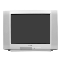
Sony KV-34FS120 Specifications

General IconGeneral
Screen Size34 inches
Display TypeCRT
Resolution480i
Aspect Ratio4:3
Comb Filter3D Digital Comb Filter
Speakers2
InputsComposite, S-Video, Component
Audio Output10W x 2

Summary

SERVICE MANUAL BA-6 CHASSIS

HISTORY INFORMATION

Provides historical context and update details for the manual.

SPECIFICATIONS

SRS (SOUND RETRIEVAL SYSTEM)

Explains the SRS Sound Retrieval System technology used.

SUPPLIED AND OPTIONAL ACCESSORIES

SUPPLIED ACCESSORIES

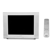
Lists items included with the television package.

OPTIONAL ACCESSORIES

Lists accessories available for separate purchase.

SAFETY WARNINGS AND CAUTIONS

SAFETY CHECK-OUT AND LEAKAGE TESTING

AC LEAKAGE TEST AND EARTH GROUNDING

Details procedures for checking AC leakage and verifying earth ground.

SELF-DIAGNOSTIC FUNCTION OPERATION

DIAGNOSTIC TEST INDICATORS AND RESULTS

Lists diagnostic items, flash counts, probable causes, and symptoms.

SECTION 1: DISASSEMBLY PROCEDURES

CHASSIS AND REAR COVER REMOVAL

Covers the removal of the rear cover and the main chassis assembly.

PICTURE TUBE AND ANODE CAP REMOVAL

Details the safe removal of the picture tube and anode cap, including warnings.

CABLE WIRE DRESSING PROCEDURES

KV-27FS320 MODELS CABLE WIRE DRESSING

Instructions for routing wires in KV-27FS320 models.

SECTION 2: SET-UP ADJUSTMENTS

BEAM LANDING ADJUSTMENT

Explains how to adjust beam landing for proper picture alignment.

CONVERGENCE ADJUSTMENTS

Covers procedures for adjusting vertical and horizontal picture convergence.

FOCUS ADJUSTMENT

Explains how to adjust the focus control for a sharp picture.

SCREEN (G2) AND WHITE BALANCE ADJUSTMENTS

Covers adjustments for screen grid voltage and white balance.

SERVICE ADJUSTMENT MODE OPERATION

Details how to enter, operate, and save settings in service mode.

SECTION 3: SAFETY RELATED ADJUSTMENTS

HV HOLD-DOWN CONFIRMATION AND READJUSTMENT

Details the HV hold-down confirmation and readjustment procedure.

B+ VOLTAGE CONFIRMATION AND ADJUSTMENT

Covers B+ voltage confirmation and adjustment for safety.

SECTION 4: CIRCUIT ADJUSTMENTS

SERVICE MODE AND REMOTE COMMANDER OPERATION

Explains how to set up service mode and use remote commander functions.

SERVICE DATA LISTS

Provides initial data values for various service adjustments.

ID MAP TABLE FOR MODEL CONFIGURATION

Maps models and destinations to specific ID settings.

A BOARD ADJUSTMENTS

Details various adjustments performed on the A Board for optimal performance.

PICTURE GEOMETRY AND LINEARITY ADJUSTMENTS

Details adjustments for vertical/horizontal size, center, linearity, and trapezoid.

V. ANGLE, BOW, AND PIN ADJUSTMENTS

Explains how to adjust vertical angle, bow, upper, and low pin settings.

SECTION 5: DIAGRAMS AND SCHEMATICS

CIRCUIT BOARDS LOCATION AND REFERENCE INFO

Identifies component locations and explains diagrammatic notations.

BLOCK DIAGRAM AND SCHEMATICS

Presents system block diagrams and schematic illustrations.

A BOARD SCHEMATICS AND VOLTAGE LISTS

Provides schematic diagrams and voltage lists for the A Board.

HM BOARD SCHEMATICS

Provides schematic diagrams for the HM Board, noting repair limitations.

V BOARD SCHEMATICS AND VOLTAGE LISTS

Presents schematic diagrams and voltage lists for the V Board.

M BOARD SCHEMATICS

Provides schematic diagrams for the M Board.

M BOARD VOLTAGE LISTS

Lists IC and transistor voltage values for the M Board.

C BOARD SCHEMATICS AND VOLTAGE LISTS

Provides schematic diagrams and voltage lists for the C Board.

HN, HR, AND HS BOARD SCHEMATICS

Presents schematic diagrams for the HN, HR, and HS boards.

HU/HD BOARD SCHEMATIC DIAGRAM

Provides schematic diagrams for the HU/HD boards.

SEMICONDUCTOR COMPONENTS

Illustrates common semiconductor components used in the service manual.

SECTION 6: EXPLODED VIEWS

CHASSIS EXPLODED VIEW (27/32/36FS320 MODELS)

Exploded view of the chassis assembly for specific models.

PICTURE TUBE EXPLODED VIEW (27/32/36FS320 MODELS)

Exploded view of the picture tube and related components for specific models.

CHASSIS EXPLODED VIEW (32/34/36/38FS120 MODELS)

Exploded view of the chassis assembly for specific models.

PICTURE TUBE EXPLODED VIEW (32/34/36/38FS120 MODELS)

Exploded view of the picture tube and related components for specific models.

SECTION 7: ELECTRICAL PARTS LIST

CAPACITORS AND CONNECTORS PARTS LIST

Lists capacitors and connectors with part numbers and values.

DIODES, TRANSISTORS, AND RESISTORS PARTS LIST

Lists diodes, transistors, and resistors with part numbers and values.

TRANSFORMERS, COILS, ICs, AND MISCELLANEOUS PARTS LIST

Lists transformers, coils, ICs, and other miscellaneous parts.

Related product manuals