Do you have a question about the Sony KV-XA25M31 and is the answer not in the manual?
Lists symptoms, causes, and detected issues related to the standby/timer lamp flashes.
Explains how to interpret the flash counts of the standby/timer lamp.
How to display past failure occurrences on the screen.
How to clear diagnostic results and quit the self-diagnostic screen.
Explains the circuit diagram for self-diagnosis.
General warnings and safety precautions for using the TV.
Instructions for connecting the antenna and VCR.
Instructions for inserting batteries into the remote control.
Guide to automatic channel presetting.
Explains how to connect optional audio/video components.
Steps for connecting a DVD player via video or component input.
Methods to secure the TV to prevent falling.
Shortcut method to select TV program numbers.
Quick reference for common TV operations like volume, mute, video input.
Instructions on how to change the menu language.
How to set the TV to turn on automatically at a specific time.
How to set the TV to turn off automatically after a set period.
Explains selecting picture and sound modes.
How to choose and adjust different picture modes.
How to choose and adjust different sound modes.
How to display and select favorite TV channels directly.
Explanation of the surround sound feature and its options.
How to enjoy stereo or bilingual sound from NICAM and A2 systems.
Explains how to access and view Teletext broadcasts.
How to quickly access Teletext pages using FASTEXT.
Overview of the TV's menu system and how to navigate it.
Explains how to change picture settings like mode, wide mode, and intelligent pic.
Explains how to change sound settings like mode, surround, and intelligent volume.
Changing menu language, picture position, program setup, and color system.
Adjusting TV channel presets, including automatic and manual tuning.
Explains the self-diagnosis function and how to interpret indicators.
Guide to solving common TV viewing problems like snowy picture or noisy sound.
Solutions for stereo sound issues and muted sound.
Solutions for picture slant, lines on screen, and Teletext display problems.
Quick checks for antenna connection and signal issues.
Checks for antenna direction, type, and wall connection for optimal viewing.
Identifies and explains the functions of TV front panel controls.
Explanation of remote control buttons and their functions.
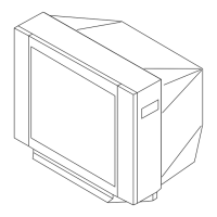
Steps for removing the rear cover of the TV.
Steps for removing the speakers.
Steps for removing the main chassis assembly.
Steps for removing the F bracket.
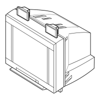
How to place the TV in a service position for adjustments.
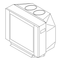
Procedures for replacing specific parts like light guide and power button.
Instructions for replacing the light guide.
Instructions for replacing the power button.
Steps for removing HV cap block, PWB holder, and J board.
Steps for removing the terminal bracket.
Steps for removing B1, P2, and V1 boards.
Steps for removing the H board.
Steps for removing A and B boards.
Steps for removing the picture tube.
Procedures for handling and removing the anode cap.
Important handling procedures for the anode cap.
Specific steps for safely removing the anode cap.
How to reset the TV settings to their original condition.
Explains the purpose of the reset function.
Method to access the reset function.
Describes the result of the reset operation and remaining settings.
When to perform these critical setup adjustments.
Steps for adjusting beam landing for optimal picture alignment.
Preparatory steps before making beam landing adjustments.
Steps for adjusting horizontal and vertical static convergence.
Preparatory steps before starting convergence adjustments.
Detailed procedures for static convergence adjustments.
Procedures for dynamic convergence adjustment.
Preparatory steps for dynamic convergence adjustment.
Adjusting convergence for screen corners.
Steps for adjusting the focus of the picture.
Steps for adjusting the G2 (screen) control.
Procedures for adjusting white balance settings.
Adjusting sub bright settings for optimal picture.
Adjustments using the remote commander.
How to enter the TV's service mode.
How to exit service mode and return to TV mode.
How to save adjustment data into memory.
How to confirm that adjustments were saved.
General method for performing adjustments and writing data.
Comprehensive table of adjustable items, functions, and settings.
Table listing adjustable items, functions, and their settings.
Table listing adjustable items, functions, and their settings.
Details specific settings related to OPB0 and OP1 configurations.
Details specific settings related to OPB1 and OP2 configurations.
Details specific settings related to OPB2 and OP3 configurations.
Details specific settings related to OPB3 and OP4 configurations.
Steps for adjusting sub color settings.
Steps for adjusting sub hue settings.
Deflection adjustments for normal mode at 50Hz.
Deflection adjustments for wide mode at 50Hz.
Deflection adjustments for normal mode at 60Hz.
Deflection adjustments for wide mode at 60Hz.
Adjusting H-Trapezoid distortion for optimal picture.
Specific adjustments needed for the A board after replacing IC003.
Adjustments to correct various picture distortions.
Further adjustments to correct picture distortions.
Overall block diagram showing the TV's system architecture.
Diagrams showing the physical location of circuit boards.
Detailed schematic diagram of the H board.
Detailed schematic diagram of the A board.
Detailed schematic diagram of the C6 board.
Detailed schematic diagram of the B1 board.
Detailed schematic diagram of the VM1 board.
Schematic diagrams of the F and J boards.
Detailed schematic diagram of the J1 board.
List of parts and their codes for the A board.
List of parts and their codes for the B board.
List of parts and their codes for the J1 board.
Voltage list for the A board (part 1/2).
Voltage list for the A board (part 2/2).
Voltage list for the B board (part 1/2).
Voltage list for the B board (part 2/2).
Voltage list for the C6 board.
Voltage list for the VM1 board.
Voltage list for the V1 board.
Voltage list for the B1 board.
Voltage list for the H board.
Voltage list for the P2 board (part 2/2).
Voltage list for the P2 board (part 1/2).
Waveform examples for the A board.
Waveform examples for the C6 board.
Printed wiring board layout for the A board.
Printed wiring board layout for the B board.
Printed wiring board layout for the H board.
Printed wiring board layout for the J1 board.
Printed wiring board layout for the B1 board.
Printed wiring board layout for the C6 board.
Printed wiring board layout for the V1 board.
Printed wiring board layout for the VM1 board.
Printed wiring board layout for the F board.
Printed wiring board layout for the J board.
Printed wiring board layout for the P2 board (component side).
Printed wiring board layout for the P2 board (conductor side).
List of components on the P2 A board.
List of components on the P2 B board.
Diagrams and identifiers for various diodes.
Diagrams and identifiers for various transistors.
Identification and diagrams for integrated circuits.
Exploded view of the picture tube assembly and its parts.
Exploded view of the chassis assembly and its components.
Important notes about part stocking and critical components.
List of electrical parts for board A.
Comprehensive list of electrical parts used in the TV.
Waveform examples from the A board.
Waveforms from the C6 board.
Printed wiring board layout for the A board.
Printed wiring board layout for the B board.
Printed wiring board layout for the H board.
Printed wiring board layout for the J1 board.
Printed wiring board layout for the B1 board.
Printed wiring board layout for the C6 board.
Printed wiring board layout for the V1 board.
Printed wiring board layout for the VM1 board.
Printed wiring board layout for the F board.
Printed wiring board layout for the J board.
Printed wiring board layout for the P2 board (component side).
Printed wiring board layout for the P2 board (conductor side).
List of components on the P2 A board.
List of components on the P2 B board.
Diagrams and identifiers for various diodes.
Diagrams and identifiers for various transistors.
Identification and diagrams for integrated circuits.
Exploded view of the picture tube assembly and its parts.
Exploded view of the chassis assembly and its components.
Important notes about part stocking and critical components.
List of electrical parts for board A.