EasyManua.ls Logo

Sony MDR-IF5K - Page 6

Sony MDR-IF5K
20 pages
Print Icon
To Next Page IconTo Next Page
To Previous Page IconTo Previous Page
Loading...
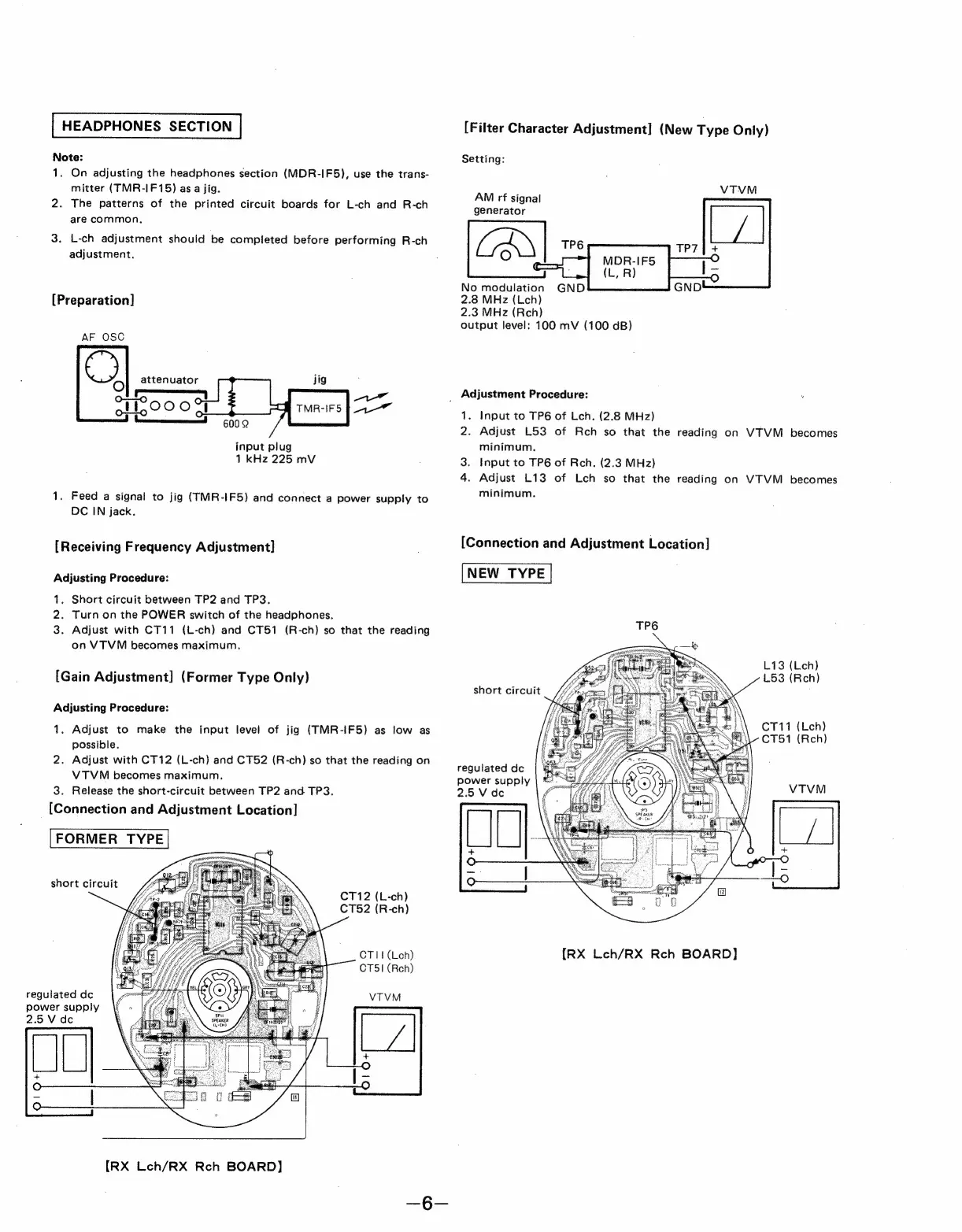
regulated
dc
power
supply
HEADPHONES
SECTION
Note:
1.
On
adjusting
the
headphones
section
(MDR-IFS5),
use
the
trans-
mitter
(TMR-IF15)
as
a
jig.
2.
The
patterns
of
the
printed
circuit
boards
for
L-ch
and
R-ch
are
common.
3.
L-ch
adjustment
should
be
completed
before
performing
R-ch
adjustment.
[Preparation]
AF
OSC
€)
attenuator
O
_—_—_—_—_—
\\
input
plug
1
kHz
225
mV
1.
Feed
a
signal
to
jig
(TMR-IF5)
and
connect
a
power
supply
to
DC
IN
jack.
[Receiving
Frequency
Adjustment]
Adjusting
Procedure:
1.
Short
circuit
between
TP2
and
TP3.
2.
Turn
on
the
POWER
switch
of
the
headphones.
3.
Adjust
with
CT11
(L-ch)
and
CT51
(R-ch)
so
that
the
reading
on
VTVM
becomes
maximum.
[Gain
Adjustment]
(Former
Type
Only)
Adjusting
Procedure:
1.
Adjust
to
make
the
input
level
of
jig
(TMR-IF5)
as
low
as
possible.
2.
Adjust
with
CT12
(L-ch)
and
CT52
(R-ch)
so
that
the
reading
on
VTVM
becomes
maximum.
3.
Release
the
short-circuit
between
TP2
and
TP3.
[Connection
and
Adjustment
Location]
FORMER
TYPE
CT12
(L-ch)
CT52
(R-ch)
CTI!
(Lech)
CT5I
(Roh)
VTVM
(RX
Leh/RX
Rch
BOARD]
[Filter
Character
Adjustment]
(New
Type
Only)
Setting:
AM
rf
signal
generator
No
modulation
GND
2.8
MHz
(Lch)
2.3
MHz
(Rch)
output
level:
100
mV
(100
dB)
_
Adjustment
Procedure:
1.
Input
to
TP6
of
Lch.
(2.8
MHz)
2.
Adjust
L53
of
Rech
so
that
the
reading
on
VTVM
becomes
minimum.
3.
Input
to
TP6
of
Rech.
(2.3
MHz)
4.
Adjust
L13
of
Lch
so
that
the
reading
on
VTVM
becomes
minimum.
[Connection
and
Adjustment
Location]
NEW
TYPE
L13
(Leh)
L53
(Rech)
short
circuit
CT11
(Leh)
CT51
(Rech)
regulated
dc
power
supply
2.5
V
de
[RX
Lch/RX
Rch
BOARD]