Sony Corporation © 2002 Printed in Japan
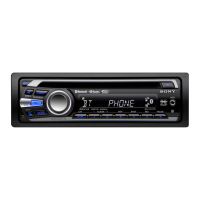
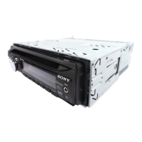
MEX-5DI
3-242-050-11 (1)
Cautions
• This unit is designed for negative ground 12 V DC
operation only.
• Do not get the wires under a screw, or caught in
moving parts (e.g. seat railing).
• Before making connections, turn the car ignition
off to avoid short circuits.
• Connect the yellow and red power input leads
only after all other leads have been connected.
• Run all ground wires to a common ground
point.
• Be sure to insulate any loose unconnected wires
with electrical tape for safety.
• The use of optical instruments with this product
will increase eye hazard.
Notes on the power supply cord (yellow)
• When connecting this unit in combination with
other stereo components, the connected car
circuit’s rating must be higher than the sum of
each component’s fuse.
• When no car circuits are rated high enough,
connect the unit directly to the battery.
Before installation (1)
Do not install the unit where its operation interferes
with driving.
Example:
— Opening and closing of the front panel or disc
tray interfere with operation of the gear shift.
— With the front panel open, operation of hazard
lamps, switches etc., is impaired.
Part s Iist (2)
The numbers in the list are keyed to those in the
instructions.
For the use of release key 7, see the supplied
operating instructions.
Caution
Handle the bracket
1 carefully to avoid
injuring your fingers.
Installat ion/Connections
Installat ion/Connexions
Instalación/Conexiones
MG-MS/FM/AM
Compact Disc
Player
Connection exam ple (3)
Note (3-A)
Be sure to connect t he ground cord bef ore connecting
the amplif ier.
Tip (3-B-
)
For connecting t w o or more CD/MD changers, t he source
selector XA-C30 (opt ional) is necessary.
Connection diagram (4)
1 To a metal surface of the car
First connect t he black ground lead, t hen connect
the yellow and red pow er input leads.
2 To the power antenna control lead or power
supply lead of antenna booster amplifier
Notes
• It is not necessary to connect t his lead if there is no
power antenna or ant enna booster, or w it h a
manually-operat ed t elescopic antenna.
• When your car has a built -in FM/AM antenna in
the rear/side glass, see “ Notes on the cont rol and
power supply leads.”
3 To AMP REMOTE IN of an optional power
amplifier
This connection is only f or amplifiers. Connecting
any other system may damage t he unit .
4 To the interface cable of a car telephone
5 To a car’s illumination signal
Be sure to connect t he black ground lead t o it first.
6 To the +12 V power terminal which is energized
in the accessory position of the ignition key
switch
Notes
• If there is no accessory posit ion, connect t o t he +12
V power (batt ery) t erminal which is energised at all
times.
Be sure to connect t he black ground lead t o it first.
• When your car has a built -in FM/AM antenna in
the rear/side glass, see “ Notes on the cont rol and
power supply leads.”
7 To the +12 V power terminal which is energised
at all times
Be sure to connect t he black ground lead t o it first.
Notes on the control and pow er supply leads
• The pow er antenna control lead (blue) supplies +12 V
DC when you turn on t he tuner.
• When your car has built-in FM/AM antenna in t he rear/
side glass, connect t he pow er antenna control lead
(blue) or the accessory power input lead (red) t o the
power terminal of t he existing antenna boost er. For
details, consult your dealer.
• A power antenna w it hout relay box cannot be used
with this unit .
M emory hold connection
When the yellow pow er input lead is connect ed, pow er
will always be supplied to t he memory circuit even when
the ignit ion key is t urned off.
TOP
32
Equipment used in illustrations (not supplied)
Appareils utilisés dans les illustrations (non fournis)
Equipos ut ilizados en las ilust raciones (no suministrados)
Rear speaker
Haut-parleur arrière
Altavoz trasero
Front speaker
Haut-parleur avant
Altavoz delantero
2
Active subwoofer
Caisson de graves actif
Altavoz potenciador de graves activo
54
CD/MD changer
Changeur de CD/MD
Cambiador de CD/MD
× 4
1
3
B
BUS AUDIO IN
BUS CONTROL IN
BUS AUDIO IN
BUS CONTROL IN
Source selector*
Sélecteur de source*
Selector de fuente*
XA-C30
* not supplied
non fourni
no suministrados
SUB OUT (M ONO)
A
121 (4
7
/8)
19 (
3
/4)
59 (2
3
/8)
170 (6
3
/4)
142.5 (5
5
/8)
Dimensions include unit size, front panel and disc tray open, etc.
Les dimensions comprennent l’appareil lui-même, la façade et le plateau de disque lorsqu’ils sont
ouverts, etc.
Las dimensiones incluyen el tamaño de la unidad, el panel frontal y la bandeja de discos abierta, etc.
1
Unit: mm (in.)
Unité : mm (po.)
Unidad: mm
× 2
TOP
Power amplifier
Amplificateur de puissance
Amplificador de potencia
76
9.5 (
3
/8)
AUDIO OUT
FRONT
AUDIO OUT
REAR
Downloaded from: https://www.usersmanualguide.com/