45
MEX-N5100BE/N5100BT/N5150BT
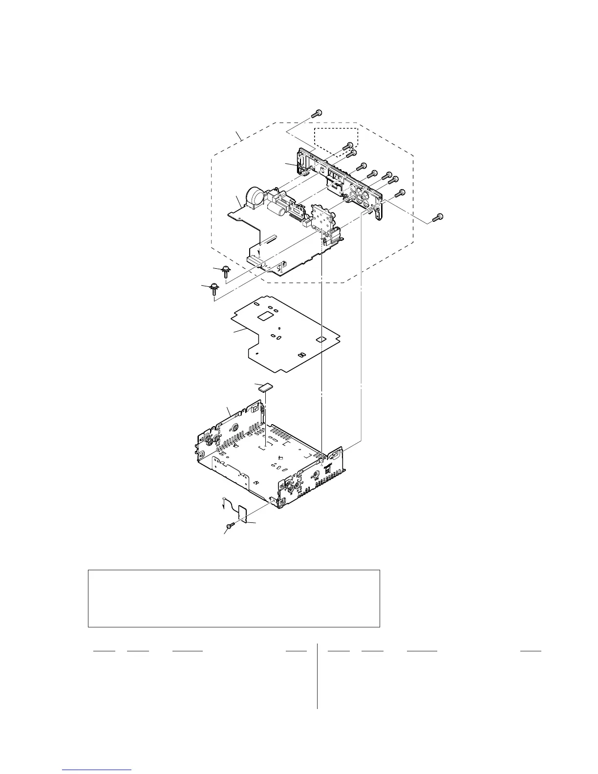
6-2. CHASSIS SECTION
51 3-042-244-01 SCREW (T)
52 4-548-823-01 SHEET HEAT TRANSFER
53 4-410-504-01 SCREW (+PTT 2.6X6), GROUND POINT
54 A-2063-242-A MAIN BOARD, COMPLETE (US, CND) (See Note)
54 A-2063-243-A MAIN BOARD, COMPLETE (Except US, CND)
(See Note)
BT1 1-754-894-21 BT, ANTENNA
#3 7-685-793-01 SCREW +PTT 2.6X8 (S)
#4 7-685-794-01 SCREW +PTT 2.6X10 (S)
#5 7-685-134-19 SCREW +P 2.6X8 TYPE2 NON-SLIT
Ref. No. Part No. Description Remark Ref. No. Part No. Description Remark
D
not supplied
not supplied
52
MAIN
board
not supplied
#4
#4
#4
#5
#5
#5
#4
#
#3
53
53
54
(US, CND)
D
51
BT1
Note: When the complete MAIN board is replaced, it is necessary to replace knob (VOL) (SV)
assy simultaneously. Also, the destination setting, Bluetooth operation check and Blue-
tooth information writing is necessary. Refer to “DESTINATION SETTING METHOD”
on page 4, “BLUETOOTH FUNCTION CHECKING METHOD USING A CELLULAR
PHONE” on page 7 and “BLUETOOTH INFORMATION WRITING METHOD” on
page 8.


 To Next Page