Do you have a question about the Sony MZ-R2 and is the answer not in the manual?
Guidance on handling chip components during repair.
Instructions for repairing flexible circuit boards.
Warning about safety-critical components and replacement.
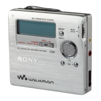
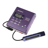
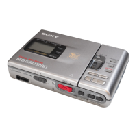
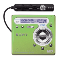
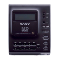
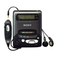
Identifies and explains the recorder's controls and display.
Guide to unpacking and initial setup for operation.
Explains options for powering the device (AC, battery).
Instructions for connecting and recording from digital/analog sources.
Details on recording using a microphone.
Basic steps for playing an MD.
Explains repeat modes for playback.
Advanced tips for playing, like Hold and AVLS.
Procedures for erasing recorded tracks.
How to connect the MD recorder to audio systems.
Lists and explains common error messages.
Explains the MiniDisc technology and format.
Procedure for disassembling the lid cover.
Disassembly of the main board and motors.
Disassembly of the mechanism deck.
Disassembly of sled motor and optical pick-up.
Overview and methods for entering the test mode.
Describes displays and modes within the test mode.
Details on the Servo Mode operations and structure.
Details on the Audio Mode operations and structure.
Details on the Mechanism Mode operations and structure.
Details on the Power Mode operations and structure.
Safety precautions for checking laser diode emission.
Precautions for handling the optical pick-up block.
General precautions before performing adjustments.
Procedure for adjusting laser power.
Procedure for offset adjustment.
Procedure for MO traverse adjustment.
Procedure for MO P-TOC traverse adjustment.
Method for checking MO error rate.
Procedure for CD traverse adjustment.
Procedure for adjusting CD RF level.
Method for checking CD error rate.
Identifies key points for adjustment and connection.
Lead layouts for various semiconductor components.
Pin assignments and functions for key ICs.
Overall system block diagram.
Layouts of printed wiring boards.
Schematic diagram for RF/Servo section.
Schematic diagram for Process section.
Schematic diagram for Audio section.
Schematic for Micro Computer/MD section.
Block diagrams for individual ICs.
Exploded view of the cabinet assembly.
Exploded view of the main board assembly.
Exploded view of mechanism deck part 1.
Exploded view of mechanism deck part 2.
List of capacitors with part numbers and specifications.
List of resistors with part numbers and specifications.
List of diodes, transistors, and ICs with details.
| Brand | Sony |
|---|---|
| Model | MZ-R2 |
| Category | Minidisc Recorder |
| Language | English |