Do you have a question about the Sony NSG-MR5U and is the answer not in the manual?
Instructions for qualified service personnel only, avoid electric shock.
Use isolation transformer to avoid shock hazard from live chassis.
Critical safety components identified by shading/mark; replace with specified Sony parts.
Perform safety checks before releasing the set to the customer, e.g., connections, parts.
AC leakage from exposed metal parts to earth ground must not exceed 0.5 mA.
Details HDMI, Optical, LAN, USB, IR Blaster connectivity.
Details power requirements, consumption, dimensions, mass, operating temp/humidity.
Details wireless LAN standard, frequency range, modulation, Bluetooth.
Lists supplied accessories with their part numbers.
Explains wireless LAN security options like WEP, WPA-PSK.
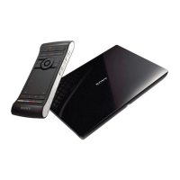
Diagram showing connections between STB, NSZ-GS7, TV, and AV Receiver.
Visual guide for diagnosing common issues like No Power, Blinking LEDs, etc.
Troubleshooting steps for no power, involving checking components like G Board, wire harness, MS Board.
Troubleshooting for power LED blinking errors, including specific blink counts and causes.
Steps for resolving a 10-blink error, suggesting software update or MS Board check.
Steps for resolving an 11-blink error, involving UR Board or MS Board replacement.
Troubleshooting for no picture, checking HDMI cable and FUSE F1900.
Troubleshooting for no sound, checking audio output priority and SPDIF/HDMI cables.
Troubleshooting steps for remote commander issues, including battery, pairing, wireless module.
Troubleshooting for wired and wireless network connection issues.
Troubleshooting steps for USB connection problems, suggesting software update or MS Board check.
Detailed steps for resetting the remote commander, dependent on its availability.
Step-by-step instructions with images for removing the top cover.
Instructions for removing the UR board and Wi-Fi module.
Steps to remove the switching regulator (G Board) from the bottom cover.
Instructions for removing the MS Board, including heat sink and thermal pad replacement.
Instructions on how to properly route internal wires, especially antenna cables.
Shows the internal layout and wire routing for the entire unit.
Illustrates the proper routing of antenna cables.
Important cautions for routing grey and black antenna cables.
Cautions for routing the white antenna cable from the BT antenna.
Diagram showing all parts with reference numbers and part numbers.
Lists and identifies various cables and connectors with their part numbers.
Identifies Fuse F1900 and its part number.
Lists supplied accessories and packing items with part numbers.
Lists different remote commander models and their corresponding regions.
Outlines required steps for servicing, including software update and factory reset.
Instructions for downloading and installing the latest software update via USB.
Detailed steps for installing the software update using the Connect button and Android Recovery screen.
Steps to perform a factory reset after software update to remove customer data.
How to check the installed software version and system information.
Tests to perform before shipping to ensure proper functionality (LAN, USB, Wi-Fi, etc.).
Instructions for resetting the remote commander based on whether it was returned with the unit.
Steps to reset the original remote commander using specific button combinations.
Steps to pair and reset a new remote commander for the unit.
How to access service mode for diagnostics and log copies.
Identifies the location of major circuit boards within the unit.
Explains symbols and notations used in schematics.
High-level diagram showing component interactions and data flow.
Detailed schematic diagram of the G Board.
Detailed schematic of the MS Board, part 1 of 18.
Detailed schematic of the MS Board, part 2 of 18.
Detailed schematic of the MS Board, part 3 of 18.
Detailed schematic of the MS Board, part 4 of 18.
Detailed schematic of the MS Board, part 5 of 18.
Detailed schematic of the MS Board, part 6 of 18.
Detailed schematic of the MS Board, part 7 of 18.
Detailed schematic of the MS Board, part 8 of 18.
Detailed schematic of the MS Board, part 9 of 18.
Detailed schematic of the MS Board, part 10 of 18.
Detailed schematic of the MS Board, part 11 of 18.
Detailed schematic of the MS Board, part 12 of 18.
Detailed schematic of the MS Board, part 13 of 18.
Detailed schematic of the MS Board, part 14 of 18.
Detailed schematic of the MS Board, part 15 of 18.
Detailed schematic of the MS Board, part 16 of 18.
Detailed schematic of the MS Board, part 17 of 18.
Detailed schematic of the MS Board, part 18 of 18.
Detailed schematic diagram of the UR Board.
Guidelines for handling, repairing, and replacing encryption key components.
| Device Type | Media Player |
|---|---|
| Model | NSG-MR5U |
| Category | Media Player |
| Manufacturer | Sony |
| Remote Control | Yes |
| Power Source | AC Adapter |
| Supported Media Formats | MP3, MPEG-4, AVI |
| Connectivity | Ethernet |