Do you have a question about the Sony PCM-1630 and is the answer not in the manual?
Details the steps for repacking the unit for shipping or storage.
Instructions for mounting the unit into a standard rack system.
Guidance on how to safely remove the unit's outer casing.
Procedure for removing the heat sink assembly for maintenance.
Important safety notes for replacing the PS-81 board and fuses.
Pinout configurations for diodes, transistors, and ICs.
Overview of block diagrams for key internal circuit boards.
Schematic and component layout for the AD-23 board.
Detailed list and diagrams of replaceable parts.
Comprehensive list of electrical components.
List of accessories included with the unit.
Information on changes to electrical parts for updated models.
Overview of the unit's high-performance recording and playback capabilities.
Technical details and performance parameters of the PCM-1630.
List of compatible recorders, editors, and analyzers for system integration.
Important safety and operational guidelines before use.
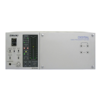
Identification and description of front panel components and their functions.
Description and pin assignments of rear panel connectors.
Information on the location and access to internal circuit boards.
Procedure for setting recording levels, reference signals, and headroom.
Guidance on system connections and basic operational procedures.
System configuration for high-precision digital-to-digital editing.
System configuration for high-precision digital editing using DAE-1100A.
Setup for four-channel recording and playback using synchronized units.
Procedure for recording and playing back SMPTE time code for editing.
Overview of the unit's internal block diagram sections.
Diagrams illustrating data and emphasis signal flow.
Details on composite digital (video) and digital I/O signal formats.
Recommended methods for synchronizing the unit with external equipment.
Instructions for repacking the unit for shipping or storage.
Steps for installing the unit into a rack using slide rails.
Guidance on safely removing the unit's top, side, and front panels.
Procedure for removing the heat sink assembly.
Safety precautions for replacing PS-81 board regulators and fuses.
List of necessary test equipment for electrical adjustments.
Procedure for adjusting voltage outputs on the PS-81 board.
Steps for calibrating the analog-to-digital conversion levels.
Procedures for adjusting DA conversion and analog output parameters.
Calibration steps for composite digital output and clock signals.
Procedure for adjusting sync and data extraction levels.
Pinout configurations for various semiconductor components.
Functional block diagram of the AD-23 board.
Functional block diagram of the DA-15 board.
Functional block diagram of the ENC-2 board.
Functional block diagram of the SIF-1 board.
Functional block diagram of the DEC-15 board.
Functional block diagram of the MT-16 board.
Component layout diagram for the AD-23 board.
Component layout diagram for the DA-15 board.
Component layout diagram for the ENC-2 board.
Component layout diagram for the SIF-1 board.
Component layout diagram for the DEC-15 board.
Component layout diagram for the MT-16 board.
Guidelines for ordering replacement parts.
Detailed diagrams and lists of all replaceable parts.
List of electrical components for various boards.
List of accessories provided with the unit.
Details of component updates and changes in electrical parts lists.
| Type | Digital Audio Processor |
|---|---|
| Manufacturer | Sony |
| Model | PCM-1630 |
| Audio Format | PCM |
| Sampling Frequency | 44.1 kHz |
| Quantization | 16-bit |
| Digital Interface | AES/EBU, S/PDIF |
| Synchronization | Word Clock |
| Frequency Response | 20 Hz to 20 kHz |
| Signal-to-Noise Ratio | Greater than 90 dB |
| Dynamic Range | Greater than 90 dB |
| Analog Inputs | 2 XLR |
| Analog Outputs | 2 XLR |
| Power Supply | AC 100-240V |
| Dimensions | 19" x 1.75" x 10.5" |