Do you have a question about the Sony PlayStation 2 SCPH-30002 R and is the answer not in the manual?
Critical safety warnings for components marked with a symbol.
Procedures for ensuring set safety and quality after repair.
Methods and limits for measuring AC leakage current.
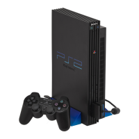
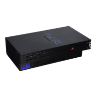
Console power, dimensions, and mass details.
Exploded diagram of the main assembly for the SCPH-30001 R model.
Exploded diagram of the main assembly for SCPH-30002/30003/30004 R.
Detailed exploded diagram of the MiniDisc drive assembly.
Exploded diagram illustrating the GH mount assembly.
Exploded diagram of the Shield (A) assembly.
Exploded diagram of the console's switch assembly.
Exploded view of the power switch, fan, and rear panel components.
Exploded view of MD, GB mount, and plate assemblies.
| Model | SCPH-30002 R |
|---|---|
| Manufacturer | Sony |
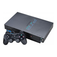
| Type | Home Video Game Console |
| CPU | Emotion Engine |
| CPU Clock Speed | 294.912 MHz |
| GPU | Graphics Synthesizer |
| GPU Clock Speed | 147.456 MHz |
| RAM | 32 MB |
| Video RAM | 4 MB |
| Media | DVD-ROM, CD-ROM |
| Power Supply | Internal |
| Storage | Memory Card |
| Video Output | Composite, S-Video, Component |
| Audio Output | Stereo |
| Ports | 2x USB, 1x AV Multi Out |