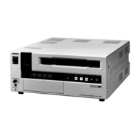
Do you have a question about the Sony Professional U-matic SP BVU-950 and is the answer not in the manual?
Specifies recommended operational environment conditions to ensure unit performance and maintenance access.
Details physical dimensions and clearance requirements for unit installation and ventilation.
Lists the technical specifications of the BVU-950, including mechanical, electrical, and video parameters.
Identifies the location of key mechanical components and printed circuit boards within the unit.
Provides circuit information, detailing the function of each printed circuit board in the system.
Outlines daily checks for system control functions like playback, rewind, and shuttle operations.
Provides instructions for cleaning video heads, stationary heads, and tape path areas.
Details the procedure for removing and installing the unit's outer casing and panels.
Explains how to service specific printed circuit boards, including removal and replacement.
Step-by-step guide for replacing the upper drum assembly, including necessary tools and procedures.
Instructions for replacing various heads, including audio/CTL, time code, and full erase heads.
Covers adjustments related to the reel table system, including cassette holder and reel table height.
Details adjustments for the threading system, such as ring rotation and gear box installation.
Explains how to adjust the torque of the S brake using measurement tools and specific procedures.
Provides instructions for adjusting the slantness of the T correction guide for proper tape path alignment.
Outlines the sequence of operations for performing tracking adjustments on the video system.
Details the procedure for adjusting DC voltage regulator outputs for proper system operation.
Covers the adjustment of D/A amplitude for proper servo system operation.
Explains how to adjust the drum's free speed for optimal servo performance.
Describes how to set the audio recording level for optimal input signal quality.
Details the procedure for adjusting the playback frequency response of the audio system.
Outlines the first part of the playback RF frequency response adjustment for the video system.
Describes the tentative phase equalizing adjustment for conventional video modes.
Explains how to adjust the time code playback level using specific test signals and equipment.
Covers the adjustment of character size for superimposed text on the video signal.
| Video Format | U-matic SP |
|---|---|
| Tape Width | 3/4 inch |
| Video Heads | 2 |
| Audio Channels | 2 |
| Editing Capability | Yes |
| Horizontal Resolution | 300 lines |
| Audio Tracks | 2 |
| Signal System | NTSC/PAL |
| Signal-to-Noise Ratio | 48 dB (video) |
| Inputs | Composite Video, Audio |
| Outputs | Composite Video, Audio |
| Power Supply | AC 100-240V |
