
H
Hannah RileySep 9, 2025
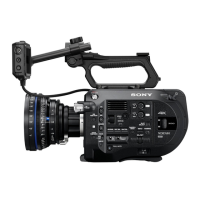
What to do if memory error of IC1700 on the DPR-365 board appears on Sony PXW-FS7K Camcorder?
- MMichael HubbardSep 9, 2025
If your Sony Camcorder displays a memory error of IC1700 on the DPR-365 board, you should replace the DPR-365 board.