EasyManua.ls Logo

Sony RDR-HX980 User Manual

Sony RDR-HX980
123 pages
To Next Page IconTo Next Page
Page #1 background imageLoading...
Page #1 background image
SERVICE MANUAL
DVD RECORDER
Sony Corporation
Home Electronics Network Company
9-883-980-11
2008D1600-1
©2008.04
Published by Quality Assurance Dept.
SPECIFICATIONS
RDR-HX680/HX780/HX785/
HX980/HX1080
RMT-D246A/D249P/D250P
AEP Model
RDR-HX680/HX780/HX785/HX980/
HX1080
Canadian Model
UK Model
E Model
RDR-HX780
Australian Model
Russian Model
Singapore Model
Thai Model
RDR-HX780/HX980
Photo: RDR-HX780
RMT-D246A
(AEP)
Ver. 1.0 2008.04
(AEP, UK, Russian)
System
Laser: Semiconductor laser
Channel coverage:
PAL (
AEP, UK, Russian model
B/G, D/K, I)/SECAM (L)
VHF: E2 to E12, R1 to R12, F2 to
F10, Italian A to H, Ireland A to J,
South Africa 4 to 11, 13
UHF: E21 to E69, R21 to R69, B21 to
B69, F21 to F69
CATV: S01 to S05, S1 to S20, France
B to Q
HYPER: S21 to S41
The above channel coverage merely ensures
the channel reception within these ranges. It
does not guarantee the ability to receive
signals in all circumstances. The channels
that can be received differ depending on the
country/region.
Video reception: Frequency
synthesizer system
Audio reception: Split carrier system
Aerial out: AEP, UK, Russian model
Antenna out: Canadian, E model
Channel coverage:
Canadian, E model
NTSC
VHF: 2 to 13
UHF: 14 to 69
CATV: A8 to A1, A to W, W+1 to W+84
75-ohm asymmetrical aerial
socket
Timer: Clock: Quartz locked/Timer
indication: 24-hour cycle (digital)
Video recording format: MPEG-2,
MPEG-1
Audio recording format/applicable
bit rate: Dolby Digital 2 ch
256 kbps/128 kbps (in EP, SLP, and
SEP mode), PCM
Inputs and outputs
LINE 2
LINE OUT: Canadian, E model
OUT: AEP, UK, Russian model
(AUDIO): Phono jack/2 Vrms/10 kilohms
(VIDEO): Phono jack/1.0 Vp-p
(S VIDEO): 4-pin mini DIN/Y: 1.0 Vp-p,
C
C: 0.286 Vp-p (NTSC)
: 0.3 Vp-p (PAL)
LINE 2
LINE IN 1/2/3: Canadian, E model
IN: AEP, UK, Russian model
(AUDIO): Phono jack/2 Vrms/more than
22 kilohms
(VIDEO): Phono jack/1.0 Vp-p
(S VIDEO): 4-pin mini DIN/Y: 1.0 Vp-p,
C: 0.3 Vp-p (PAL)
LINE 3 – TV: 21-pin
CVBS OUT
S-Video/RGB OUT (upstream)
LINE 1/DECODER: 21-pin
CVBS IN/OUT
S-Video/RGB IN
Decoder
DV IN: 4-pin/i.LINK S100
DIGITAL OUT (COAXIAL): Phono
jack/0.5 Vp-p/75 ohms
COMPONENT VIDEO OUT
(Y, P
B/CB, PR/CR):
(Y, P
B, PR):
AEP, UK, Russian model
Canadian, E model
Phono jack/Y: 1.0 Vp-p,
P
B/CB: 0.7 Vp-p, PR/CR: 0.7 Vp-p
G-LINK*: mini jack
HDMI OUT: HDMI™ Connector
USB:
USB jack Type A (For connecting
digital still camera, Memory card
reader, USB memory and HDD
camcorder)
USB jack Type B (For connecting
PictBridge-compatible printers)
General
Power requirements: 220-240 V AC,
50/60 Hz
Power consumption:
43 W AEP, UK, Russian model
42 W Canadian, E model
Dimensions (approx.):
430 66.5 286.5 mm (width/height/
depth) incl. projecting parts
Hard disk drive capacity:
RDR-HX680/HX780/HX785:
160 GB
RDR-HX980: 250 GB
RDR-HX1080: 500 GB
Mass (approx.): 4.4 kg
Operating temperature: 5ºC to 35ºC
Operating humidity: 25% to 80%
Supplied accessories:
Mains lead (1)
Aerial cable (1)
Re
Audio/video card (1) Canadian, E model
mote commander (remote) (1)
Set top box controller (1)*
R6 (size AA) batteries (2)
*RDR-HX780/HX785/HX980/HX1080
Specifications and design are subject to
change without notice.
AEP model only
w
w
w
.
x
i
a
o
y
u
1
6
3
.
c
o
m
Q
Q
3
7
6
3
1
5
1
5
0
9
9
2
8
9
4
2
9
8
T
E
L
1
3
9
4
2
2
9
6
5
1
3
9
9
2
8
9
4
2
9
8
0
5
1
5
1
3
6
7
3
Q
Q
TEL 13942296513 QQ 376315150 892498299
http://www.xiaoyu163.com

Table of Contents

Question and Answer IconNeed help?

Do you have a question about the Sony RDR-HX980 and is the answer not in the manual?
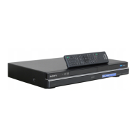
Sony RDR-HX980 Specifications

General IconGeneral
BrandSony
ModelRDR-HX980
CategoryDVD Recorder
LanguageEnglish

Summary

SERVICE MANUAL & SPECIFICATIONS

SPECIFICATIONS

Detailed technical specifications for various models, including system, inputs, outputs, and general power requirements.

SAFETY AND WARNINGS

LASER SAFETY WARNING

Precautions regarding safe handling and proximity to the laser exit to prevent eye injury from radiation.

SAFETY CHECK-OUT PROCEDURE

Steps to perform after repairs to ensure the unit's safety before customer release.

SECTION 1 SERVICE NOTES AND PROCEDURES

SERVICE MODES AND DIAGNOSTICS

SERVICE MODE MAP

Overview of available service modes and their operational pathways accessed via the remote control.

DIAGNOSTIC MODES

Detailed procedures for accessing various diagnostic modes like Model Setting, HDD, DV, and EPG.

SERVICE NOTE: DISK AND BOARD PROCEDURES

DISK REMOVAL PROCEDURE

Instructions for forced disk removal when the tray cannot eject normally.

MODEL NAME SETTING METHOD

HDD FAILURE DIAGNOSIS

DEFECTIVE HDD SYMPTOMS

Identifies common symptoms of HDD failure, such as error codes E01/E02 and freezing playback.

HDD RECOGNITION STATUS AND SUBSCREEN MODE

How to enter HDD recognition status and relevant subscreen modes for diagnosis.

DIAGNOSIS FLOWCHART FOR E01 ERROR

DIAGNOSIS FLOWCHARTS FOR E02 AND FREEZING ISSUES

E02 ON FLD DISPLAY

Flowchart for diagnosing and resolving the "E02" error related to HDD authorization or system data errors.

VIDEO/MP3/JPG FREEZING

Troubleshooting steps for issues where media playback freezes without error display.

FINAL CHECKS AND FACTORY PROCEDURES

FACTORY CHECK AND HDD SELF TEST

Procedures for factory checks, including formatting, and executing the HDD Self Test (SMART TEST).

HDD DIAGNOSTIC TESTS

PERFORMANCE CHECK

Procedure for performing a reading test across all HDD sectors to detect errors.

POWER BLOCK DIAGRAM

SCHEMATIC DIAGRAMS AND WAVEFORMS

AV-133 BOARD SCHEMATICS

AV-134 BOARD SCHEMATICS

RD-066 BOARD SCHEMATICS

POWER BLOCK

Schematic diagram of the power block for the RD-066 board, showing voltage regulation and distribution.

SWITCHING REGULATOR SCHEMATICS

SRV-2101EK SCHEMATIC

Schematic diagram for the SRV-2101EK switching regulator, detailing its circuit and voltage outputs.

SECTION 6 SERVICE MODE OPERATIONS

SERVICE MODE MAP AND PREPARATION

Overview of service mode access, required tools, and the service mode operational map.

DIAGNOSTIC MODES

Procedures for Model Setting, Service Mode access, RF Level Diagnosis, and HDD Information retrieval.

HDD INFORMATION AND ERROR LOGGING

Steps to retrieve HDD info for return, handle HDD safely, and access HDD error logs.

SECTION 7 ADJUSTMENTS

Related product manuals