Do you have a question about the Sony SS-CCP300 and is the answer not in the manual?
Precautions for handling the optical pick-up block to prevent damage.
Guidelines for safely checking laser diode emission.
Information on identifying different model variations and voltage selectors.
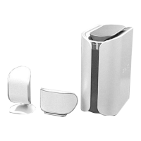
Diagram and labels for the main unit's controls and indicators.
Procedure for removing the top cover of the unit.
Steps for disassembling the front panel assembly.
Steps for accessing and removing the main circuit board.
Disassembly instructions for the CD mechanism deck.
Mode to position pick-up for shipping or vibration resistance.
Mode for checking software version, LEDs, and system parameters.
Mode to run CD sled motor freely for cleaning or maintenance.
Procedure for adjusting the head azimuth for optimal playback.
Procedure for adjusting tape playback speed.
Procedure to check and adjust focus bias for CD playback.
Overall block diagram of the CD playback system.
Block diagram of the main processing and control sections.
Detailed schematic for the CD playback circuitry.
Schematic for the tape control and audio processing circuits.
Main section schematic part 1, covering power and amplifier controls.
Schematic for the power supply and voltage regulation circuits.
Details on pin functions for key integrated circuits.
Block diagrams illustrating the internal functions of major ICs.
Exploded view of the outer cover and related parts.
Exploded view of the front panel assembly and its components.
Exploded view of the main chassis and structural components.
Exploded view of the CD mechanism deck, showing parts.
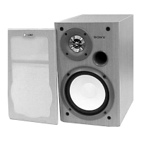
| Type | Speaker System |
|---|---|
| Brand | Sony |
| Model | SS-CCP300 |
| Impedance | 6 Ohms |
| Speaker Units | 2-way |