Do you have a question about the Sony SS-TSF500 and is the answer not in the manual?
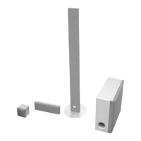
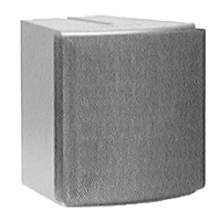
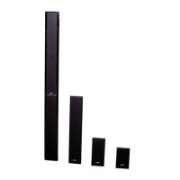
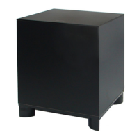
Details of technical specifications for the speaker system and subwoofer models.
Provides a block diagram of the DSP section, illustrating signal flow and components.
Block diagram illustrating the DVD servo section's circuitry.
Presents a block diagram of the amplifier section, detailing signal paths.
Block diagram of the main section, showing connections to various components.
Shows a block diagram of the power supply section, outlining its functional blocks.
Block diagram illustrating the HDMI and video signal paths.
Block diagram of the panel and power supply sections.
Illustrates the component layout on the AMP-DSP board from the component side.
Shows the component layout on the AMP-DSP board from the conductor side.
Provides the first part of the AMP-DSP board schematic diagram.
Displays the second part of the AMP-DSP board schematic diagram.
Presents the third and final part of the AMP-DSP board schematic diagram.
Illustrates the wiring layout for the SPEAKER board.
Provides the schematic diagram for the SPEAKER section.
Lists pin functions for IC704 and IC705 on the AMP-DSP board.
Lists integrated circuits used on the DMB-FIT board, including part numbers and descriptions.
Warns about safety-critical components and the need for specific replacement parts.
Explains the self-diagnosis function and how to interpret error codes.
Executable test modes without entering the main test menu.
Explains DVD service mode for diagnosis and adjustment.
Step-by-step guide to access the DVD service mode via the remote and TV screen.
Procedures for manual adjustment of various optical disc parameters.
Instructions on how to check the system's emergency history and error codes.
Procedure for checking FM tuner level and signal reception.
Illustrates the component layout on the DMB-FIT board (part 1 of 2).
Provides the first part of the DMB-FIT board schematic diagram.
Displays the second part of the DMB-FIT board schematic diagram.
Presents the third part of the DMB-FIT board schematic diagram.
Shows the fourth and final part of the DMB-FIT board schematic diagram.
Provides the first part of the MAIN board schematic diagram.
Displays the second part of the MAIN board schematic diagram.
Presents the third and final part of the MAIN board schematic diagram.
Displays waveforms for key signals on the DMB-FIT board.
Lists pin functions for IC101 on the DMB-FIT board.
Continues the pin function description for IC101 on the DMB-FIT board.
| Brand | Sony |
|---|---|
| Model | SS-TSF500 |
| Category | Speaker System |
| Language | English |