EasyManua.ls Logo

Sony SS-WS551 User Manual

Sony SS-WS551
150 pages
To Next Page IconTo Next Page
Page #1 background imageLoading...
Page #1 background image
SERVICE MANUAL
9-874-058-01 Sony Corporation
2002G0500-1 Home Audio Company
C 2002.07 Published by Sony Engineering Corporation.
Ver 1.0 2002.07
COMPACT AV SYSTEM
DAV-C770 DAV-C990
SACD/DVD RECEIVER HCD-C770 HCD-C990
FRONT SPEAKER SS-TS503 SS-TS551
CENTER SPEAKER SS-TS503 SS-CT551
REAR SPEAKER SS-TS503 SS-TS551
SUB WOOFER SS-WS503 SS-WS551
PACKAGE SPEAKER SS-WT503 SS-C990
US Model
Canadian Model
DAV-C770/C990
AEP Model
Australian Model
DAV-C770
•DAV-C770/C990 are composed of following models.
As service manuals are issued for each component model, please refer to them.
COMPONENT MODEL NAME
1-477-372-11 COMMANDER, STANDARD (RM-SS990)
1-754-060-13 ANTENNA (FM) (C770: AEP, Australian)
1-754-147-11 ANTENNA (FM) (C770: US, Canadian/C990)
1-754-149-11 LOOP ANT (AM)
1-769-108-11 CORD, CONNECTION (VIDEO CORD)
1-824-622-11 CORD (WITH CONNECTOR) (RED)
(for FRONT R SPEAKER)
1-824-622-21 CORD (WITH CONNECTOR) (PURPLE) (for SUB WOOFER)
1-824-622-31 CORD (WITH CONNECTOR) (WHITE)
(for FRONT L SPEAKER)
1-824-622-41 CORD (WITH CONNECTOR) (GRAY)
(for REAR R SPEAKER)
1-824-622-51 CORD (WITH CONNECTOR) (BLUE)
(for REAR L SPEAKER)
1-824-622-61 CORD (WITH CONNECTOR) (GREEN)
(for CENTER SPEAKER)
1-824-180-11 CORD, CONNECTION (21PIN ADAPTER) (AEP)
4-241-068-11 MANUAL, INSTRUCTION (ENGLISH) (C770)
4-241-068-21 MANUAL, INSTRUCTION (FRENCH) (C770: Canadian, AEP)
4-241-068-31 MANUAL, INSTRUCTION (GERMAN, SPANISH, DUTCH,
SWEDISH, ITALIAN, POLISH) (C770: AEP)
4-241-068-41 MANUAL, INSTRUCTION (DANISH, FINNISH,
PORTUGUESE) (C770: AEP)
4-241-068-51 MANUAL, INSTRUCTION (GREEK) (C770: AEP)
4-241-071-11 MANUAL, INSTRUCTION (ENGLISH) (C990)
4-241-071-21 MANUAL, INSTRUCTION (FRENCH) (C990: Canadian)
4-243-416-01 BATTERY COVER (for RM-SS990)
4-243-457-01 RUBBER (SPEAKER) (for SPEAKER)
PARTS LIST
Part No. Description Remark
DAV-C770/C990
SPECIFICATIONS
General
Power requirements
North American model: 120 V AC, 60 Hz
European model: 230 V AC, 50/60 Hz
Australian model: 220 – 240 V AC, 50/60 Hz
Power consumption 135
140 W (120 V AC) (DAV-C990)
W (120 V AC) 135 W (230 V AC) (DAV-C770)
1 W (120 V AC) 2 W (230 V AC) (at the Power Saving Mode)
Dimensions (approx.) 355 × 70 × 335 mm (14 × 2
7
/
8
× 13
1
/
4
inches: DAV-C770)
(14 × 2
7
/
8
× 15 inches: DAV-C990) (w/h/d) incl. projecting parts
Mass (approx.) 4.4 kg (9 lb 12 oz)
Operating temperature 5˚C to 35˚C (41˚F to 95˚F)
Operating humidity 5 % to 90 %
Supplied accessories
Design and specifications are subject to change without notice.
• Speakers (5)
• Subwoofer (1)
• AM loop antenna (1)
• FM wire antenna (1)
• Speaker cords (5m × 4, 15m × 2) (17ft. × 4, 50ft. × 2)
• Video cord (1)
• Remote Commander (remote) RM-SS990 (1)
• R6 (size AA) batteries (2)
• Foot pads (20)
• Speakers-connection and Installation (card) (1)
• 21-pin Adapter (1) (Only for the European models)

Table of Contents

Question and Answer IconNeed help?

Do you have a question about the Sony SS-WS551 and is the answer not in the manual?

Sony SS-WS551 Specifications

General IconGeneral
BrandSony
ModelSS-WS551
CategorySpeaker System
LanguageEnglish

Summary

Service Manual

SACD/DVD Receiver Specifications

Servicing Notes

Chip Component Replacement Notes

Provides guidance on reusing, handling, and replacing chip components.

Flexible Circuit Board Repairing

Offers tips on soldering iron temperature and handling flexible boards during repair.

Laser Radiation Caution

Warns about hazardous radiation exposure from controls or procedures not specified.

Safety Check-out Procedures

Details safety checks like AC leakage testing after service.

Optical Pick-up Handling Notes

Provides precautions for handling the optical pick-up block to prevent electrostatic breakdown.

Laser Diode Emission Check Notes

Guides on how to safely check the laser diode emission, maintaining a safe distance.

DVD Board Replacement Note

Explains the procedure for initializing memory after replacing the DVD board.

Disassembly Procedure

Disassembly Flowchart

Provides a step-by-step diagram for disassembling the unit.

Assembly Procedure

Installing the Cam (Eject Lock)

Details the procedure for installing the cam for eject lock, including gear engagement.

Installing the Cam (Gear)

Explains how to install the cam (gear), aligning marks and ensuring proper rotation.

Test Mode Operations

Starting Test Mode

Details the procedure to enter the test mode using the power button and remote.

Operating Test Mode

Outlines how to select and execute various diagnostic and adjustment functions.

Drive Auto Adjustment

Details the automatic adjustment process for DVD-SL, CD, and DVD-DL discs.

DVD-SL Auto Adjustment Steps

Lists the step-by-step procedure for adjusting DVD single layer discs.

CD Auto Adjustment Steps

Lists the step-by-step procedure for adjusting CD discs.

DVD-DL Auto Adjustment Steps

Details the step-by-step procedure for adjusting DVD dual layer discs.

Drive Manual Operation Mode

Explains the manual operation mode for servo on/off control and adjustments.

Disc Type Setup and Check

Covers automatic disc type checking and manual setting for various disc formats.

Servo Control Operations

Details how to control and adjust servos (LD, Focus, Spindle, Tracking, Sled).

Non-EEPROM Write Adjustment

Describes manual adjustment of various parameters without writing to EEPROM.

EEPROM Write Adjustment

Details automatic adjustment of parameters and writing values to EEPROM.

EEPROM Memory Check

Explains how to view and clear stored servo adjusted data in EEPROM.

Mecha Aging Test

Details the process of executing mechanism deck aging tests, including open/close tests.

Mecha Error History

Explains how to access and interpret mechanism deck error history codes.

Electrical Adjustments

Video Level Adjustment

Explains how to perform video level adjustment using color bars on the OSD.

Auto Servo Adjustment

Details the necessity and procedure for re-adjusting the servo circuit after parts replacement.

RF Level Check Procedure

Describes how to check the RF signal waveform and level using an oscilloscope.

Circuit Diagrams

IC301 CXP973064R Pin Function Description

Details the function of each pin for the CXP973064R mechanism controller IC.

IC401 CXD3068Q Pin Function Description

Lists the function of each pin for the CXD3068Q Digital Signal Processor IC.

IC701 CXD1882R Pin Function Description

Details the function of each pin for the CXD1882R DVD Decoder IC.

IC901 µPD703033BYGF Pin Function Description

Details the function of each pin for the µPD703033BYGF System Controller IC.

IC902 PT3000 Pin Function Description

Details the function of each pin for the PT3000 Changer Controller IC (Motor, Switch).

IC906 PT3000 Pin Function Description

Details the function of each pin for the PT3000 Changer Controller IC (Rotary Encoder).

Exploded Views

Mechanism Deck Section 1 Exploded View

Shows the exploded view of the mechanism deck, including stocker motor, gears, and pulleys.

Mechanism Deck Section 4 Exploded View

Details the exploded view of the mechanism deck, showing levers, gears, and screws.

Mechanism Deck Section 5 Exploded View

Illustrates the exploded view of the mechanism deck, showing gears, belts, and pulleys.

Mechanism Deck Section 6 Exploded View

Details the exploded view of the mechanism deck, including cams, levers, and shutter mechanisms.

Optical Pick-up Section Exploded View

Shows the exploded view of the optical pick-up unit, including screws and flexible boards.

Electrical Parts List

Service Manual (Speaker System)

Speaker System Specifications

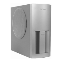
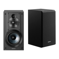
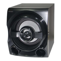
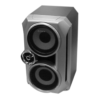
Provides specifications for speaker systems like SS-C990, SS-TS551, SS-WS551, SS-CT551.

SS-CT551 Center Speaker Exploded View

Shows an exploded view of the SS-CT551 center speaker, detailing its parts.

SS-TS551 Front/Rear Speaker Exploded View

Details the exploded view of the SS-TS551 front/rear speaker, including stand and foot parts.

SS-WS551 Subwoofer Exploded View

Shows the exploded view of the SS-WS551 subwoofer, detailing its cover, panels, and base parts.

Related product manuals