EasyManua.ls Logo

Sony TC-WE471 User Manual

Sony TC-WE471
35 pages
To Next Page IconTo Next Page
Page #1 background imageLoading...
Page #1 background image
Page TC-WE305 (US model) TC-WE471
Ref. No. Part No. Description Ref. No. Part No. Description
17 EXPLODED VIEWS EXPLODED VIEWS
*************** ***************
* 6 3-935-621-01 PANEL, BACK * 6 3-935-621-61 PANEL, BACK
18 53 A-2004-584-A PANEL ASSY, FRONT 53 A-2004-624-A PANEL ASSY, FRONT
Sony Corporation
Home A&V Products Company
TC-WE471
US Model
SERVICE MANUAL
MICROFILM
9-960-889-11
STEREO CASSETTE DECK
Printed in USA ©1997.3
TC-WE471 is similar to the earlier TC-WE305 (US) model.
• Refer to TC-WE305 service manual (9-960-691-XX) for information not
contained in this service manual.
DIFFERENCE TABLE
NOTE:
Items marked “*” are not stocked since they are seldom required for
routine service. Some delay should be anticipated when ordering
these items.
Question and Answer IconNeed help?

Do you have a question about the Sony TC-WE471 and is the answer not in the manual?

Sony TC-WE471 Specifications

General IconGeneral
Track System4-track, 2-channel stereo
Tape Speed4.8 cm/s
TypeDouble Cassette Deck
Heads2 x erase
MotorDC servo
Tape TypeCrO2, Metal
Noise ReductionDolby B

Summary

Specifications

Model Identification

Safety Check-out

Leakage Test

Procedures for testing AC leakage from exposed metal parts to earth ground.

Safety-Related Component Warning

Warning about critical safety components identified by mark A.

Section 1 General

Identifying the Parts

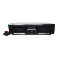
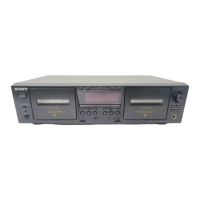
Visual identification of various components and controls on the unit.

Section 2 Disassembly

Front Panel Removal

Step-by-step instructions for removing the front panel assembly.

Mechanism Deck Removal

Step-by-step instructions for removing the mechanism deck.

Section 3 Adjustments

Mechanical Adjustments

Procedures for adjusting mechanical parts like torque and tape tension.

Electrical Adjustments

Procedures for adjusting electrical parameters like record bias and playback levels.

Section 4 Diagrams

Printed Wiring Boards

Diagrams showing the layout of components on the printed circuit boards.

Schematic Diagram

Electrical schematic diagrams illustrating the circuit layout of the unit.

Section 5 Exploded Views

Chassis Section

Exploded view of the main chassis and associated components.

Front Panel Section

Exploded view of the front panel assembly and its parts.

Mechanism Deck Section 1

Exploded view of the first part of the tape mechanism deck.

Mechanism Deck Section 2

Exploded view of the second part of the tape mechanism deck.

Section 6 Electrical Parts List

Related product manuals