EasyManua.ls Logo

Sony STR-DE545 Service Manual

Sony STR-DE545
48 pages
To Next Page IconTo Next Page
Page #1 background imageLoading...
Page #1 background image
1
STR-DE445/DE545/SE501
US Model
STR-DE445/DE545/SE501
Canadian Model
AEP Model
UK Model
STR-DE445/DE545
E Model
Australian Model
Chinese Model
PX Model
STR-DE545
FM STEREO FM-AM RECEIVER
SERVICE MANUAL
SPECIFICATIONS
Dolby Laboratories Licensing Corporation.
“DOLBY” the double-D symbol ; “AC-3” and “PRO LOGIC”
are trademarks of Dolby Laboratories Licensing Corporation.
Photo: STR-DE445
AUDIO POWER SPECIFICATIONS
POWER OUTPUT AND TOTAL HARMONIC
DISTORTION
With 8 loads, both channels driven, from
20 – 20,000 Hz; rated 100
a)
W per channel
minimum RMS power, with no more than
0.09% total harmonic distortion from 250
mW to rated output (US model only).
STR-DE445:
a) 80 W
Amplifier section
Rated Power Output at Stereo mode
US model:
(8 20 Hz – 20 kHz, THD
0.09 % )
EXCEPT US:
(8 1 kHz, THD 0.7 %)
STR-DE545/SE501:
100 W + 100 W
STR-DE445:
80 W + 80 W
Reference Power Output
(8 at 1 kHz, THD 0.7 %)
STR-DE545/SE501:
Front: 100 W + 100 W
Center: 100 W
Rear: 100 W + 100 W
STR-DE445:
Front: 80 W + 80 W
Center: 80 W
Rear: 80 W + 80 W
Frequency response
CD, MD/TAPE, DVD/LD, TV/
SAT, VIDEO, AUX:
10 Hz – 50 kHz +0.5/–2 dB
(with sound field, tone, and
bass boost bypassed)
Inputs (Analog) 5.1 CH INPUT, CD, DVD/LD,
MD/TAPE, TV/SAT, VIDEO,
AUX:
Sensitivity: 250 mV
Impedance: 50 k
S/N
b)
: 96 dB (A, 250 mV
c)
)
b) Input short.
c) Weighted nework, input level.
Inputs (Digital) DVD/LD (coaxial):
Sensitivity: —
Impedance: 75
S/N: 100 dB (A, 20 kHz LPF)
DVD/LD, TV/SAT* (Optical):
Sensitivity: —
Impedance: —
S/N: 100 dB (A, 20 kHz LPF)
*) STR-DE545 and STR-SE501 only.
Outputs MD/TAPE, (REC OUT); VIDEO
(AUDIO OUT):
Voltage: 250 mV,
Impedance: 10 k
SUB WOOFER:
Voltage: 2 V
Impedance: 1 k
PHONES:
Accepts low- and high-
impedance headphones
BASS BOOST +6 dB at 70 Hz
TONE ±6 dB at 100 Hz and 10 kHz
Sampling Frequency
48 kHz
FM tuner section
Tuning range 87.5 – 108.0 MHz
Antenna terminals 75 , unbalanced
Sensitivity Mono: 18.3 dBf, 2.2 µV/75
Stereo: 38.3 dBf, 22.5 µV/75
Usable sensitivity 11.2 dBf, 1 µV/75
S/N Mono: 76 dB
Stereo: 70 dB
Harmonic distortion at 1 kHz
Mono: 0.3 %
Stereo: 0.5 %
Separation 45 dB at 1 kHz
Frequency response
30 Hz – 15 kHz
+0.5/–2 dB
Selectivity 60 dB at 400 kHz
— Continued on next page —

Other manuals for Sony STR-DE545

Question and Answer IconNeed help?

Do you have a question about the Sony STR-DE545 and is the answer not in the manual?

Sony STR-DE545 Specifications

General IconGeneral
Impedance8 ohms
Total Harmonic Distortion0.09%
Tuning RangeFM, AM
Input Sensitivity250 mV (line)
Speaker Load Impedance8 ohms
Video ConnectionsComposite
Frequency Response10 Hz - 50 kHz
Inputs4 Audio, 3 Video
Outputs2 Audio, 1 Video
Digital Inputs1 optical, 1 coaxial
Dimensions430 x 298 mm
Power Output100W per channel (8 ohms, 20 Hz - 20 kHz, THD 0.09%)

Summary

Product Specifications

Audio Power and Amplifier Specifications

Details power output, THD, and amplifier section specifications.

FM Tuner Specifications

Specifies tuning range, sensitivity, S/N, and harmonic distortion for FM tuner.

AM Tuner and General Specifications

Specifies AM tuner range and covers general system, power, and dimension specs.

Safety Check-out Procedures

AC Leakage Measurement Methods

Describes three methods to measure AC leakage current.

Section 1: General Information and Panel Layout

Front Panel Controls and Indicators

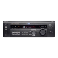
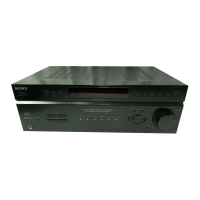
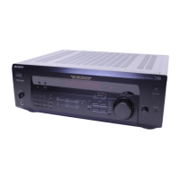
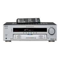
Identifies front panel buttons, knobs, and indicators with their functions.

Rear Panel Connectors and Jacks

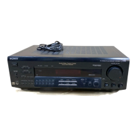
Details all input/output connectors and switches on the rear panel.

Section 2: Test Modes and System Reset

Various Test Mode Activations

Procedures for activating software version, fluorescent tube, clear, and factory modes.

Section 3: Diagrams and Schematics

Circuit Board Locations and Block Diagrams

Shows circuit board layout and high-level block diagrams.

Printed Wiring and Schematic Diagrams

Detailed diagrams for Digital, Main, Display, Video/Key, and Power Supply boards.

IC Pin Functions and Block Diagrams

Details pin functions and block diagrams for key integrated circuits.

Section 4: Exploded Views

Front Panel Exploded View

Exploded diagram showing parts of the front panel assembly.

Chassis Exploded View

Exploded diagram illustrating the chassis and internal component layout.

Section 5: Electrical Parts List

AC SEL, DIGITAL, and Main Board Parts

Lists electrical components for AC SEL, DIGITAL, and Main boards.

Other Board Components and Accessories

Lists parts for STBY, S-VIDEO, TUNER, VIDEO boards, and accessories.

Accessories and Hardware

Included Accessories List

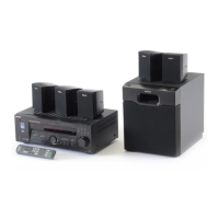
Lists included accessories such as remote commander and antenna.

Hardware List

Lists screws and other hardware supplied with the unit.

Related product manuals