EasyManua.ls Logo

Sony STR-DE505 Service Manual

Sony STR-DE505
23 pages
To Next Page IconTo Next Page
Page #1 background imageLoading...
Page #1 background image
STR+D3502/D4502/DE405/DES05
SERVICE
MANUAL
US
Model
Canadian
Model
a
Photo
:
STR-DE505
a
A
I
SPECIFICATIONS
Manufactured
under
license
from
Dolby
Amplifier
section
Se
oe
a
Laboratories
Licensing
Corporation.
Sn
Oe
Oe
eer
ne
Sy
Ra
ee
Additionally
licensed
under
Canadian
Front:
fate
STR-DES505/D450Z:
patent
number
1,037,877.
“Dolby
the
100
W/ch
io
ee
SDeine.
5m
50
:
double-D
symbol
caand
Pro
Logic”
Sean
ee
(MM)
kilohms
72
dB*
are
trademarks
of
Dolby
Laboratories
Canadian
model
:
70W/ch
(A,
2.5
mV)
.
;
STR-D3502:
CD
Licensing
Corporation.
te
ee
ewes
200
mV
Canadian
model
:
70W/ch
TAPE?
50
82dB
oe
Center:
MD,
kilohms
82dB*
Audio
power
specifications
ila
sirce
aaa
Me
150
mV
(A,
150mV)
100
5
STR-DE405:
VIDEO
POWER
OUTPUT
AND
TOTAL
US
model
:
80W
-
en
ae
ee
eae
Canadian
model
:
7
HARMONIC
DISTORTION
cee
utpus
«=
TAPE/MORECOUT:
oe
mode)
a
iepeluncsionhed
US
Model
:
aa
ria
ene
VIDEO
AUDIO
OUT:
i
2
Voltage
150
mV,
With
8
ohm
load,
both
ane
LOCIG
Impedance
10
kilohms
channels
driven,
from
20
-
eae
e)
MIX
AUDIO
OUT
20,000
Hz,
rated
100
watts
STR-DE50S
/D4502:
Saag
(STR-DE5S05/D450Z),
STR
Rasa
.
Impedance:
10
kilohms
80
watts
(STR-DE405)
or
US
model
:
80W
7
eel
igh
enpetanes
60
watts
(STR-D350Z)
per
Canadian
model
:
70W
head
phones
channel
minimum
RMS
ou
eeu
°
US
model
:
60W
_
power,
with
no
more
than
Canadian
model
:
70W
Continued
on
page
2
0.09
%
total
harmonic
Frequency
PHONO:
RIAA
distortion
from
150
response
Sago
milliwatts
to
rated
output.
CD,
TAPE/MD,
VIDEO:
10
Hz
-50
kHz
21
dB
Canadian
Model
:
20
20,000
Hz
0.09%
100W+100W
(STR-D450Z,
DE505)
20
20,000
Hz
0.09%
70W+70W
(STR-D350Z,
DE405)
FIV
STEREO)
FI
-A\
RECEIVER
SONTY.

Other manuals for Sony STR-DE505

Question and Answer IconNeed help?

Do you have a question about the Sony STR-DE505 and is the answer not in the manual?

Sony STR-DE505 Specifications

General IconGeneral
Channels5.1
Tuning rangeFM/AM
Total Harmonic Distortion0.09%
Output150 mV (line)
Speaker load impedance8 ohms
Power Output100 W per channel (8 ohms, 20 Hz - 20 kHz, 0.09% THD)
Frequency Response10 Hz
InputsCD, Tape, Video 1, Video 2
OutputsTape, Video 1
Surround outputDolby Pro Logic
Input sensitivity150 mV
Video ConnectionsComposite video

Summary

Specifications

Audio Power Specifications

Details power output and total harmonic distortion for US and Canadian models.

Amplifier Section Specifications

Lists amplifier parameters including surround mode, front, center, and rear output power.

Frequency Response

Specifies the frequency response range for the amplifier section.

FM Tuner Section Specifications

Details FM tuner range, sensitivity, S/N, and distortion.

AM Tuner Section Specifications

Details AM tuner range and antenna.

Video Section Specifications

Details video input and output specifications.

General System and Power Details

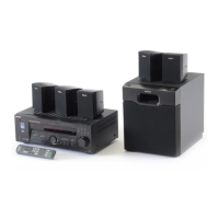
Describes system architecture and power requirements, consumption, dimensions, and mass.

Supplied Accessories

Lists items included in the package.

Safety Check-Out

Leakage Test Procedure

Explains how to test for AC leakage from exposed metal parts to earth ground.

Safety Component Warnings

Warns about critical safety components and replacement parts.

General

Location and Function of Controls

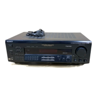
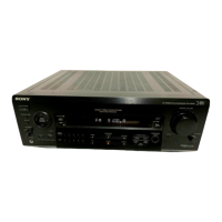
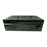
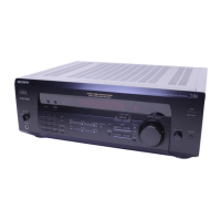
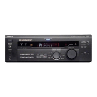
Details the controls on the front and rear panels of the receiver.

Remote Control Layout and Functions

Identifies and describes the functions of buttons on the remote control.

Explanation of IC Terminals

IC201 Terminal Pinout and Description

Explains pin assignments and functions for IC201 (µ PD78044AGF-165-3B9).

Diagrams

Circuit Board Locations Diagram

Illustrates the physical locations of various circuit boards within the unit.

Printed Wiring Board Layout - Main Section

Provides the printed wiring board layout for the main section of the unit.

Schematic Diagram - Main Section

Presents the schematic diagram for the main section of the receiver.

Schematic Diagram - Display Section

Provides the schematic diagram for the display section of the receiver.

Printed Wiring Board Layout - Display Section

Shows the printed wiring board layout for the display section.

Exploded Views

Front Panel Section Exploded View

Details the exploded view of the front panel components and their part numbers.

Chassis Section Exploded View

Presents the exploded view of the chassis components and their part numbers.

Electrical Parts List

Display Section Components

Lists capacitors, connectors, diodes, transistors, resistors, and indicator tubes for the display.

Main Section Components - Part 1

Lists resistors, switches, and capacitors for the main section of the unit.

Main Section Components - Part 2

Lists capacitors for the main section of the unit.

Main Section Components - Part 3

Lists ICs, connectors, diodes, coils, and transistors for the main section.

Main Section Components - Part 4

Lists transistors and resistors for the main section.

Main Section Components - Part 5

Lists resistors, relays, and terminals for the main section.

SP SW, Standby, and Tone Board Components

Lists components for SP SW (A), SP SW (B), SP SW, Standby, and Tone boards.

Tone, Video, and Volume Board Components

Lists components for the Tone, Video, and Volume boards.

Volume Board, Accessories, and Hardware

Lists volume board components, accessories, and hardware like screws.

Related product manuals