Do you have a question about the Sony STR-DE515 and is the answer not in the manual?
Details on RMS power output and total harmonic distortion with 8-ohm load.
Power output details for Stereo and 5.1/DVD modes across different impedance loads.
Sensitivity and impedance for various input signals.
Voltage and impedance for output signals like TAPE/MD REC OUT.
Tuning range, sensitivity, S/N, and selectivity for the FM tuner.
Procedures for checking AC leakage before releasing the unit.
Information regarding part identification and critical safety components.
Overview of the unit's controls and their functions.
Diagram showing the location of various circuit boards.
Layout of printed wiring for the main section of the unit.
Detailed schematic diagram for the main section.
Detailed schematic diagram for the display section.
Layout of printed wiring for the display section of the unit.
Exploded view of the front panel components.
Exploded view of the main chassis components.
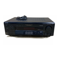
This document provides a comprehensive service manual for the Sony STR-D460Z/DE515/V505 FM Stereo/FM-AM Receiver, covering various models including US, Canadian, E, Australian, PX, and Chinese versions. The manual outlines the device's functions, usage features, and maintenance procedures, making it an essential resource for technicians and users alike.
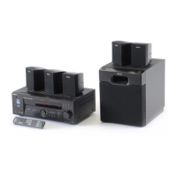
The receiver is designed to deliver a rich audio experience, functioning as a central hub for various audio and video components. It supports both FM stereo and FM-AM radio reception, allowing users to tune into a wide range of broadcasts. The device is equipped with multiple input options, including PHONO (MM), CD, 5.1/DVD, TAPE/MD, TV/DBS, and VIDEO, enabling connectivity with a diverse array of entertainment systems. This versatility ensures that users can integrate their existing devices, such as turntables, CD players, DVD players, and VCRs, into a unified home theater setup. The 5.1/DVD input specifically caters to multi-channel audio, providing an immersive surround sound experience for movies and games.
A key feature of the receiver is its robust amplifier section, which is designed to deliver powerful and clear audio output. The amplifier supports various speaker configurations, including front, center, and rear channels, to create a comprehensive surround sound environment. The manual details the power output capabilities under different impedance loads and total harmonic distortion levels, ensuring that technicians can accurately assess and maintain the amplifier's performance. The inclusion of a WOOFER/MIX AUDIO OUT allows for the connection of a subwoofer, enhancing the low-frequency response and adding depth to the audio. Additionally, a PHONES output is provided for private listening, accommodating both low and high impedance headphones.
The FM tuner section offers a broad tuning range, ensuring access to numerous radio stations. It features 75-ohm unbalanced and 300-ohm balanced antenna terminals, providing flexibility in antenna setup for optimal reception. The tuner's high sensitivity and selectivity contribute to clear and stable radio reception, even in areas with weak signals. The AM tuner section complements the FM capabilities, offering a wide tuning range for AM broadcasts. It utilizes a loop antenna for improved AM reception.
The receiver incorporates several audio processing features to enhance the listening experience. The BASS BOOST function allows users to emphasize low frequencies, adding punch and impact to music and movie soundtracks. The TONE control provides further customization of the audio output, enabling users to adjust the sound to their preferences. The device also supports surround sound modes, including Pro Logic, which creates a multi-dimensional audio field from stereo sources. This feature is particularly beneficial for enjoying older movies and TV shows with an enhanced spatial effect.
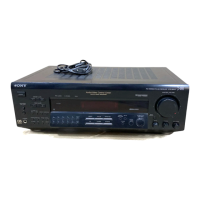
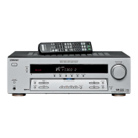
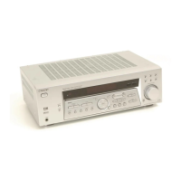
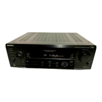
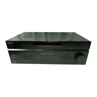
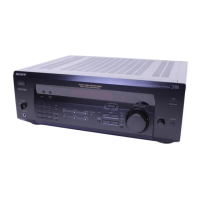
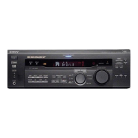
From a usage perspective, the receiver is designed for ease of operation. The front panel features clearly labeled controls for various functions, including power, input selection, volume adjustment, and tone control. The remote controller further simplifies operation, allowing users to manage the receiver from a distance. The display section provides essential information, such as the selected input, tuning frequency, and audio settings, ensuring that users can easily monitor the device's status. The manual includes detailed diagrams of the front panel and remote controller, aiding users in familiarizing themselves with the layout and functions.
Maintenance features are thoroughly covered in the service manual, providing technicians with the necessary information to diagnose and repair the device. The manual includes circuit board locations, printed wiring board diagrams, and schematic diagrams for both the main and display sections. These diagrams are crucial for tracing signal paths, identifying components, and troubleshooting electrical issues. An explanation of IC terminals is also provided, detailing the function of each pin on the integrated circuits, which is invaluable for advanced diagnostics.
The electrical parts list, organized by section (Display, Key, Main, Primary, Secondary, Selector, SP SW, STBY, Video, VR Tone), provides a comprehensive inventory of all components, including capacitors, resistors, ICs, transistors, diodes, connectors, and fuses. Each entry includes the part number, description, and relevant remarks, such as voltage, tolerance, and wattage. This detailed list is essential for ordering replacement parts and ensuring that only specified components are used for repairs, especially for safety-critical parts indicated by a special mark.
Safety check-out procedures are emphasized, requiring technicians to perform AC leakage checks after any repair to ensure the device's safety before returning it to the customer. The manual also includes instructions for identifying components with safety-critical marks on schematic diagrams and parts lists, highlighting the importance of using genuine Sony parts for these components.
The mechanical parts list, accompanied by exploded views of the front panel and chassis sections, assists in disassembling and reassembling the receiver. These diagrams show the arrangement of various mechanical components, such as buttons, holders, cases, and feet, making it easier to replace damaged parts or access internal circuitry. The color indication of appearance parts helps in identifying and ordering the correct cosmetic components.
Overall, the Sony STR-D460Z/DE515/V505 FM Stereo/FM-AM Receiver is a versatile and powerful audio-video hub designed to enhance the home entertainment experience. Its comprehensive service manual ensures that both users and technicians have access to all the necessary information for optimal operation and maintenance, guaranteeing the device's longevity and performance.
| Channels | 5.1 |
|---|---|
| Total Harmonic Distortion | 0.09% |
| Channel Separation | 50 dB |
| Tuning range | FM: 87.5 - 108 MHz, AM: 530 - 1710 kHz |
| Frequency Response | 10 Hz - 100 kHz |
| Input Sensitivity | 150mV (line) |
| Speaker load impedance | 8 ohms |
| Dimensions | 430 x 145 x 298mm |
| Inputs | 1 x phono |
| Outputs | 1 x tape |
| Power Output | 100 W per channel (8 ohms, 20 Hz - 20 kHz, 0.09% THD) |
| Signal to Noise Ratio | 100 dB (line) |