Inputs
(phono
jacks)
Input
impedance
47
k
ohms
Outputs
Line
outputs
(phono
jacks)
0.5
V
ata
load
impedance
of
47
k
ohms
Load
impedance
|
Over
10
k
ohms
Output
level
1
mW
at
a
load
impedance
of
32
ohms
US,
Canadian
model
:
120V
AC,
60Hz
UK
model
:
240V
AC,
50Hz
Australian
model
:
240V
AC,
50/60Hz
AEP,
German
model
:
220-230V
AC,
50/60Hz
E
model
:
120,
220
or
240V
AC
adjustable,
50/60Hz
25W
EXCEPT
UK,
Australian
model
:
Approx.
430
x
123
x
290
mm
(w/h/d)
(17
x
47/s
x
11
!/2
inches)
UK,
Australian
model
:
Approx.
430
123x300
mm
(w/h/d)
(17X474x
117A
inches)
including
projecting
parts
and
controls
Approx.
4.5
kg
(9
Ibs
15
0z)
Rated
output
level
Headphones
(stereo
phone
jack)
(TC-WR545
only)
General
Power
requirements
Power
consumption
Dimensions
Mass
Supplied
accessories
Audio
connecting
cords
(2)
Design
and
specifications
are
subject
to
change
without
notice.
MODEL
IDENTIFICATION
(Specification
Label)
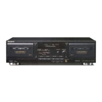
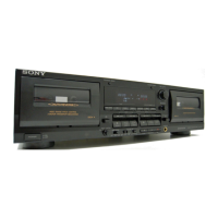
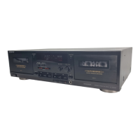
SONY:
STEREO
CASSETTE
DECK
MODEL
NO.
Rss
aaa
:
AC
120V
60Hz
US,
Canadian
model
UK
model
:
AC
240V
50Hz
Australian
model!
:
AC
240V~50/60Hz
AEP,
German
model
:
AC
220-230V~50/60Hz
E
model
:
AC120,
220,
240V~50/60Hz
TABLE
OF
CONTENTS
Section
Title
Page
Specifications
:++seresesesereeeeteeteeeeteereeteese
teeter
eseeeseees
l
Safety
Check-out
(US
Model)
SOrPereeeereeer
re
rere
rere rere
rr
eee)
3
1.
GENERAL
Identifying
the
Parts
on
the
Front
Panel
s++r+t++trrrsrrtetttteee
4
2.
DISASSEMBLY
2-1
.
Front
Panel
errr
rrr
errr tree
rere
ee
ee
eee
eee
ee
eee
5
2-2.
Mechanism
Deck
eer
rr
rrr
rer
rr
rrr
rr
errr
rere
rrr
reer
reece
5
2-3.
Capstan
Motor,
Reel
Motor
ssrrrrtrrrtrrerritrsisesessee
6
2-4.
Head,
Pinch
Rollers::sssressrereertseeeeeeeeeteeeneeeeneeeey
6
3.
ADJUSTMENTS
3-1.
Mechanical
Adjustments
:+rrrsttrrrrrereertrsereterseersersees
ay
3-2.
Electrical
Adjustments
«-++1+esseseereeeeeteeterteerierieees
7
4.
EXPLANATION
OF
IC
TERMINALS
--+-e
erste
11
5.
DIAGRAMS
5-1.
Block
Diagram
cece
ener
enon
scree
teen
rset
ne
enereeseeenonsesecure
13
522)
Circuit
Board
Location
Sererrerrrrrr
rrr
errr
errr
e
rrr
16
5-3.
Printed
Wiring
Boards
(System
Control
Section)-++++--
17
5-4.
Schematic
Diagram
(System
Control
Section):**+*+++*-
21
5-5.
Schematic
Diagram
(Audio
Section)
srrrrsrrrrtrrtttrerees
27
5-6.
Printed
Wiring
Boards
(Audio
Section):**++rstrtrrete"*
ep
6.
EXPLODED
VIEWS
6-1.
Chassis
Section
eee
e
cece
tere
nme eee
e
aren
eee
sereesenereneueeeenes
37
6-2.
Front
Panel
Section
Deemer
meen
e
nse
et
tere
an
nsosscoesesaeeeseeee
39
6-3.
Mechanism
Section
l
deere
ence
recone
eta
a
en
eee
nese
e
seen
enee
40
6-4.
Mechanism
Section
2esrrcerersssseerteseeteeeeecesessenennes
A]
7.
ELECTRICAL
PARTS
LIST
-sr--:ceecceceeceeeeseeeeeeeeeerees
42
TC-WR545,
TC-WR741
 Loading...