Do you have a question about the Sony TC-WR720A - Dual Cassette Deck and is the answer not in the manual?
Lists key performance metrics like S/N, THD, frequency response, and output levels.
Details power, physical, tape type, and mechanism specifications.
Highlights important functions like Dolby HX PRO, auto-detection, synchro dubbing, and AMS.
Outlines the methods and requirements for performing AC leakage tests on the unit.
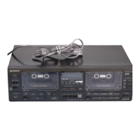
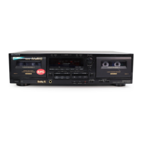
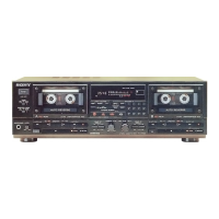
Describes the location and function of all operational controls on the unit.
Procedures for dismantling the front panel and mechanism deck of the WR720A model.
Procedures for dismantling the front panel and mechanism deck of the WR720 model.
Steps for removing motor, head, and pinch roller components during disassembly.
Details methods and values for measuring and adjusting torque on mechanical parts.
Procedures for adjusting head azimuth and tape speed for optimal playback and recording.
Covers playback level, bias consumption current, and record bias adjustments.
Details record level adjustment procedures and specified limits for accuracy.
Illustrates the physical placement of circuit boards and semiconductor lead configurations.
Shows the physical layout of printed wiring for the main sections of the device.
Provides detailed circuit schematics for audio, system control, and panel sections.
Detailed exploded views of the chassis and front panel sections for different models.
Exploded views detailing the mechanism sections, including motor and gear assemblies.
Lists capacitors, resistors, coils, and their specifications for the device.
Lists diodes, transistors, ICs, and other semiconductor components with part numbers.
Lists switches, variable resistors, connectors, and other miscellaneous components.
| Type | Dual cassette deck |
|---|---|
| Track System | 4-track, 2-channel stereo |
| Tape Speed | 4.8 cm/s |
| Power Supply | AC 120V, 60Hz |
| Weight | 4.5kg |
| Frequency Response (Normal) | 30 Hz - 14 kHz |
| Signal to Noise Ratio | 58 dB (Dolby B On) |
| Outputs | Line out |
| Dubbing Modes | Normal, High Speed |
| Noise Reduction | Dolby B |
| Dimensions (W x H x D) | 430 x 123 x 300mm |
| Frequency Response (Metal) | 30Hz to 16kHz ±3dB |