Do you have a question about the Sony TC-WR950 and is the answer not in the manual?
Checks AC leakage from exposed metal parts to earth ground. Limit is 0.5 mA.
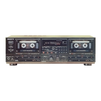
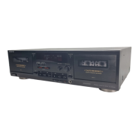
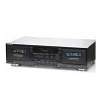
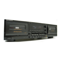
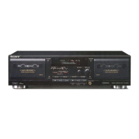
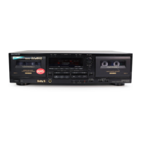
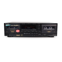
Identifies front panel, deck, and remote control functions and buttons.
Details pin functions of the mechanical control microcomputer IC701.
Details pin functions of IC951, related to display and control logic.
Provides a high-level overview of the system's functional blocks and interconnections.
Covers precautions and procedures for mechanical adjustments like torque and cleaning.
Outlines electrical adjustment procedures, including setting controls and standard signals.
Details the procedure for adjusting the head azimuth for optimal playback.
Explains how to adjust tape speed for both high and normal playback speeds.
Describes how to adjust playback output levels for L-CH and R-CH.
Details the process for adjusting erase current, crucial for recording quality.
Outlines the procedure for setting record bias for optimal frequency response.
Explains how to set recording input and output levels.
Details the adjustment procedure for the auto-reverse mechanism.
Illustrates the physical placement of components and boards on the chassis.
Provides a reference list and locations for semiconductor components.
Details the layout of the main circuit board with key components.
Troubleshooting for issues related to tape transport and button functions.
Troubleshooting for problems with recording, playback, and sound levels.
Addresses issues related to hum and recorded noise during operation.
| Track System | 4-track, 2-channel stereo |
|---|---|
| Tape Speed | 4.8 cm/s |
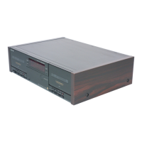
| Type | Double Cassette Deck |
| Wow and Flutter | 0.07% |
| Heads | 1 x record/playback, 1 x playback, 1 x erase |
| Motor | DC Motor |
| Input | Line In |
| Output | Line Out |
| Dimensions | 430 mm |
| Power Supply | AC 220-230V, 50/60Hz |