Do you have a question about the Sony TC-WR665S and is the answer not in the manual?
Details on recording system, bias, noise ratio, distortion, and frequency response.
Measurement of speed variations in tape playback.
Details on line inputs and outputs, sensitivity, and impedance.
Methods to test and ensure electrical safety by measuring AC leakage current.
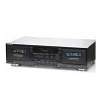
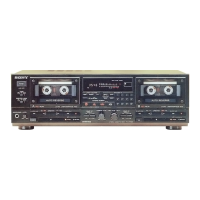
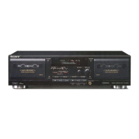
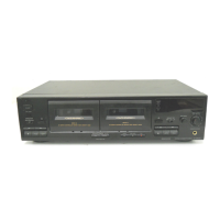
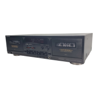
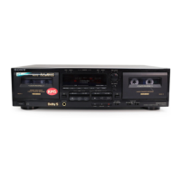
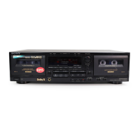
Labels and functions of controls and indicators on the front panel.
Steps to remove the front panel assembly and related components.
Procedures for disassembling the cassette mechanism deck.
Steps for removing capstan motor, reel motor, and head components.
Cleaning, demagnetizing, and torque measurement for mechanical parts.
Procedures for calibrating electrical performance using test signals.
Aligning the playback head for optimal stereo separation and frequency response.
Calibrating the tape transport speed for accurate playback and recording.
Setting the output signal level for correct playback volume.
Adjusting current for head assembly or bias transformer replacement.
Setting the recording input level for optimal signal strength.
Adjusting bias signal for proper tape recording characteristics.
Location of adjustment potentiometers on the system control board.
Location of adjustment potentiometers on the audio boards for both decks.
Location of adjustment potentiometers on the connector board.
Detailed explanation of each pin function for the main ICs used in the unit.
High-level overview of the unit's functional blocks and signal flow.
Printed wiring layout for the system control board.
Detailed circuit diagram for the system control section.
Detailed circuit diagram for the audio processing and playback sections.
Printed wiring layout for the audio boards of both decks.
Printed wiring layout for the Dolby S processing board.
Detailed circuit diagram for the Dolby S noise reduction circuitry.
Diagram showing the main chassis components and their assembly.
Diagram illustrating the assembly of the front panel and its associated parts.
Diagram showing the exploded view of the primary cassette mechanism parts.
Diagram illustrating the exploded view of secondary cassette mechanism components.
List of capacitors used in the unit, including part numbers and specifications.
List of resistors used in the unit, including part numbers and specifications.
List of transistors used in the unit, including part numbers and types.
List of integrated circuits used in the unit, including part numbers.
List of connectors, coils, filters, and other miscellaneous parts.
List of screws, bushings, and other hardware used in the assembly.
| Track System | 4-Track, 2-Channel Stereo |
|---|---|
| Tape Speed | 4.8 cm/s |
| Motor | DC Servo Motor |
| Total Harmonic Distortion | 0.8% |
| Power Supply | AC 120V, 60Hz |
| Type | Double Cassette Deck |
| Frequency Response (Normal Tape) | 30 Hz - 14 kHz |
| Frequency Response (Chrome Tape) | 30 Hz - 16 kHz |
| Frequency Response (Metal Tape) | 30 Hz - 17 kHz |
| Wow and Flutter | 0.07% |
| Output | Line Out |
| Inputs | Line In |
| Outputs | Line Out, Headphone |
| Dimensions | 430 x 120 x 300mm |