Do you have a question about the Sony WE475 - TC Dual Cassette Deck and is the answer not in the manual?
Details tape speed, signal-to-noise ratio, harmonic distortion, and frequency response.
Instructions for entering and using service mode for diagnostics and checks.
Specifies torque values for various mechanical adjustments like capstan and pinch roller.
Details on entering and using the unit's special test mode for calibration.
Procedure for adjusting head azimuth for optimal audio playback quality.
Steps for calibrating the tape playback speed to specified frequencies.
Procedure for setting the output playback signal level to a standard reference.
Adjusting bias current for head replacement or oscillator transformer.
Procedure for setting the record input signal level for optimal recording.
Adjusting bias for optimal recording performance and frequency response.
Detailed printed wiring board layout for the main control section.
Part 1 of the main section schematic diagram illustrating circuit connections.
Part 2 of the main section schematic diagram illustrating circuit connections.
Part 3 of the main section schematic diagram illustrating circuit connections.
Part 4 of the main section schematic diagram illustrating circuit connections.
Detailed pin functions for the main system control IC (IC801).
| Track System | 4-track, 2-channel stereo |
|---|---|
| Tape Speed | 4.8 cm/s |
| Noise Reduction | Dolby B |
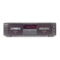
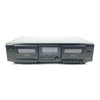
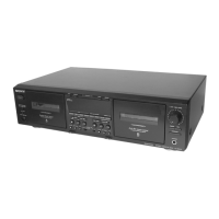
| Type | double cassette deck |
| Signal to Noise Ratio | 58dB |
| Cassette Support | Chrome |
| Outputs | line |
| Power Supply | 220V |