Do you have a question about the Sony TC-WE435 and is the answer not in the manual?
Procedure for measuring AC leakage current from metal parts.
Identifies components critical for safe operation and requires replacement with specified parts.
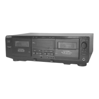
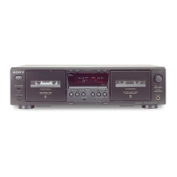
Diagram and list of front panel controls and their functions.
Procedure for removing the outer case of the unit.
Steps for disassembling the front panel assembly.
Procedure for disassembling the cassette lid for both decks.
Steps for removing the mechanism deck assembly.
Disassembly of leaf switch boards for both decks.
Procedure for disassembling pinch lever assemblies.
Steps for disassembling flywheel assemblies.
Disassembly of the main mechanical block.
Disassembly of head relay boards for both decks.
Instructions for entering and operating service mode for key and display checks.
Procedure for measuring torque on various parts like pinch rollers and belts.
Procedure for activating test mode for playback speed and counter functions.
Procedure for adjusting head azimuth for optimal playback.
Procedure for adjusting tape speed using a frequency counter.
Procedure for adjusting playback signal levels.
Adjusting bias consumption current when replacing head or bias transformer.
Procedure for setting record input and output signal levels.
Procedure for adjusting record bias levels.
Diagram showing the location of various circuit boards within the unit.
Printed wiring board layout for the main section.
Schematic diagram of the main section, part 1 of 4.
Pin functions for IC801 SYSTEM CONTROL.
Exploded view and parts list for the unit's case.
Exploded view and parts list for the tape mechanism components.
List of resistors with part numbers, values, and specifications.
List of diodes, transistors, and ICs with part numbers.
List of capacitors with part numbers, values, and specifications.
Silver model added.
| Track System | 4-track, 2-channel stereo |
|---|---|
| Tape Speed | 4.8 cm/s |
| Motor | DC Servo Motor |
| Power Supply | AC 120V, 60Hz |
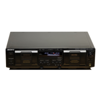
| Type | Double Cassette Deck |
| Frequency Response (Chrome Tape) | 30 Hz - 16 kHz |
| Frequency Response (Metal Tape) | 30 Hz - 17 kHz |
| Inputs | Line In |
| Outputs | Line Out, Headphones |
| Dimensions | 430 x 125 x 290 mm |